概述:在本课程中,您将学习如何使用“图纸自定义”来制作和编辑各种图纸类型和模板。
课程目标
完成本课程后,您将能够:
- 使用“图纸自定义”面板创建,编辑,复制和删除“图纸自定义”模板。
- 使用实体定制编辑器来创建,编辑和删除特定实体的模板。
- 使用各种可用的自定义设置并将其应用到所需的实体。
- 使用“规则”编辑器来设置和确定过滤器规则参数。
- 使用样式编辑器为“图形自定义”模板设置图形样式。
- 将图形自定义模板应用于视口。
- 浏览并与其他用户共享“图纸自定义”模板。
教程:深入的图纸定制
点击这里观看
关于图纸定制
PCCAD BIM使用工程图模板来自定义生成的工程图。要大致了解如何创建和使用这些模板,请访问“用于生成图纸的模板”一文。
在V21中,“图形自定义”允许您根据设置的过滤器参数规则,针对3D BIM模型中实体类型的值或属性,为图形类型创建定制模板。这对于自定义模型实体的图形(独立于其分配的层或层状态)特别有用,因此可以在具有相似实体属性的其他项目上转移和使用。
“图纸自定义”工具由3个原则(实体自定义,过滤规则和样式)操作,并且只能从面板上访问。
注意:用于图形定制的版本控制将从V21.1.06开始实施。随着功能和参数的不断改进并在将来的V21更新中添加,使用较旧版本的PCCAD打开“图形自定义”模板可能会影响其行为和性能。因此,版本控制系统将有助于防止因太旧而无法正确处理的PCCAD版本意外打开或修改自定义设置。
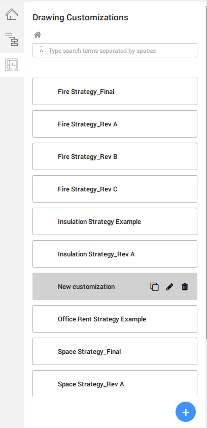
图纸自定义面板
- 右键单击面板,然后将鼠标悬停在面板上。
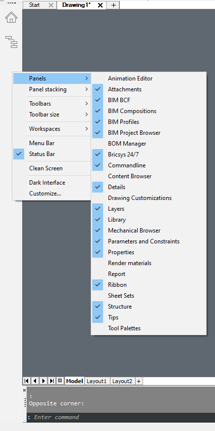
- 选择图纸定制,以停靠在面板上的工具图标。
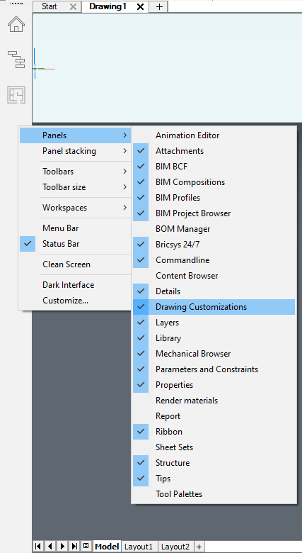
- 打开面板,它允许您创建视图模板以控制和自定义图纸在布局上的可见性设置。
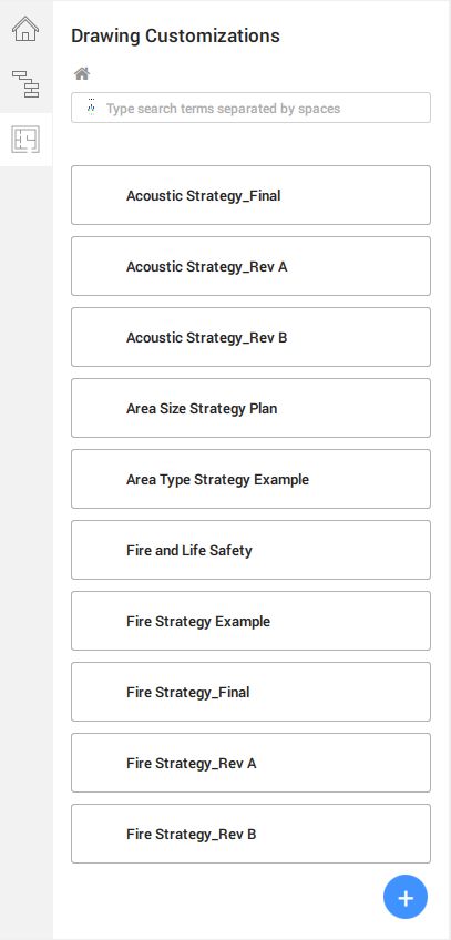
- 单击
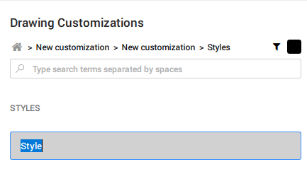
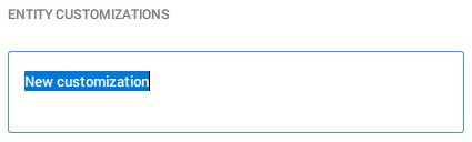
 以创建一个新模板。默认情况下,该模板名为“新自定义”,突出显示文本。
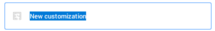
注意: “图形自定义”的所有控件在“用户界面”面板中均以图形图标表示,例如用于创建新控件。在整个工具中,它们会以不同的设置重复进行,例如实体自定义,层自定义...,但是它们的功能和目的保持一致。 - Rename the template whilst the text is being highlighted. Once done, press Enter to save and apply the name.
Note: You can duplicate, rename or delete your customization templates. - Click the newly created Drawing Customization template tab to begin defining its customization settings.
The first step into the template brings you to the Entity Customizations, where you will create the necessary entity customizations template and will be first described later in this article.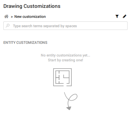
You will also notice a funnel icon and a pencil icon on the top right part of the panel. They are the Filter Rules and Styles tabs respectively.
The 3 principles – Entity Customizations, Filter Rules & Styles – which make up the Drawing Customization tool as described earlier in the article, are now accessible on this main page.
图纸自定义样式
- 单击铅笔图标以访问样式选项卡。
这是您想要的样式选项(例如线宽,线条颜色...)的存储位置,并将在下拉菜单中显示为“实体自定义”和“中心自定义”设置,如上一节中所示。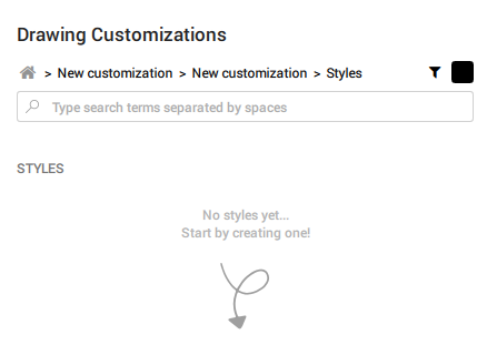
- 要创建新样式,请点击面板右下角的,然后会出现一个新的样式模板标签。
- 默认情况下,该选项卡名为Style。如图所示突出显示文本时重命名。完成后,按Enter保存并应用。
- 创建希望在此“图形自定义”模板中使用的所需样式的列表。每个选项卡都包含其各自的样式设置,例如样式的颜色,线型,线宽和线型比例。
样式示例列出了模板列表: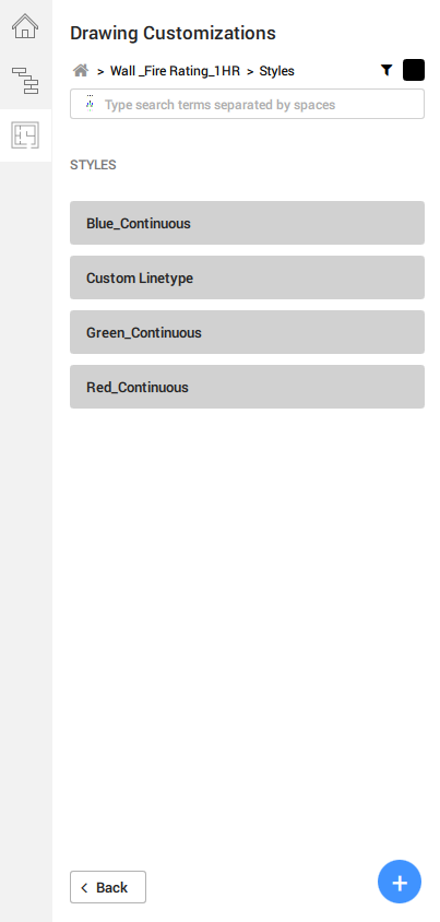
- 要编辑任何可用的样式模板,请单击其相关选项卡以访问其设置。
注意:与“图形自定义”模板选项卡相似,将鼠标悬停在样式模板选项卡上以显示要复制,重命名或删除的功能图标。
样式设置包括在其各自的下拉对话框中定义“颜色”,“线型”,“线宽”的选项。完成后,单击“确定”保存并应用更改。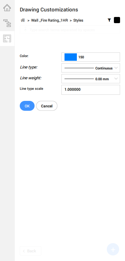
- 要退出样式页面,请单击面板左下方的“后退”以返回上一页。从那里,您可以导航以修改“实体定制”或“规则”模板。
或在搜索栏上方的树状结构图中单击所需的分支,以导航到所需的页面。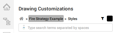
注意:树形结构图有助于使自己在“图形自定义”工具中定位。同样,如果要浏览的值很长,则搜索栏允许您缩小到特定的模板。
实体自定义
实体自定义指的是您希望如何在模型工程图中使元素看起来像的可见性设置。
- Click
- to create a new entity customization template. By default, the template is named New Customization with the text highlighted.
- Rename it whilst the text is being highlighted as shown. After you are done, hit Enter to save and apply.
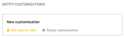
As the entity customization was newly created and not fully set up, you will find the relevant notices at the bottom of the entity customization tab. This is a helpful mechanism to remind you if any customization settings have not been defined yet, saving you the need to check the settings manually. - Create a list of templates for the entities you wish to customize.
A list of Entity Customizations templates could look like this: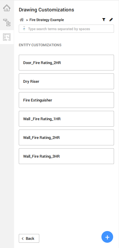
- After creating your desired entity customization templates, click onto the individual tabs to modify their respective settings.
You can choose how the element should look like as a section result, or how a centerline type representation should appear, or how an external symbol representation should replace the original entity.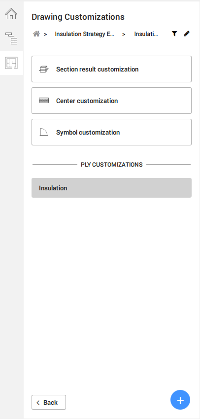
You can further modify and customize a specific ply layer of your desired entity composition, but only if appropriate, i.e. a wall, slab or roof entity. - 的部分结果定制显示了一系列对照下拉从该段的结果的图形的更具体的控制样式选项卡值。您可以使用项目中可用的预设或自定义物理材质,通过外观替代来替代实体的剖面线。
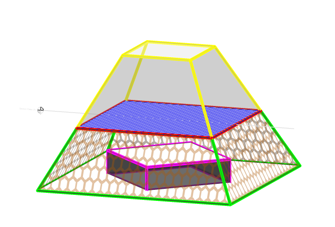
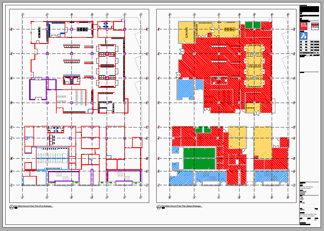
上图说明了如何使用“图形自定义”工具控制实体的可见性和自定义设置。请注意,剖面与红色轮廓的蓝色正方形对齐。
- 绿色轮廓线表示Background,它本质上是剪切对象的高程轮廓线。
- Red outline represents Intersection Boundary, which traces over the cut area.
- Blue hatch represents Intersection Fill, as it shows the area of being cut by the section plane.
- Orange hexagons hatch represents Elevation Fill, which refers to the area bound by the elevation outline (see Background).
- Pink outline represents Hidden Lines, as it is below the blue hatch
- Yellow outline represents Cut away geometry, as it is above the section plane.
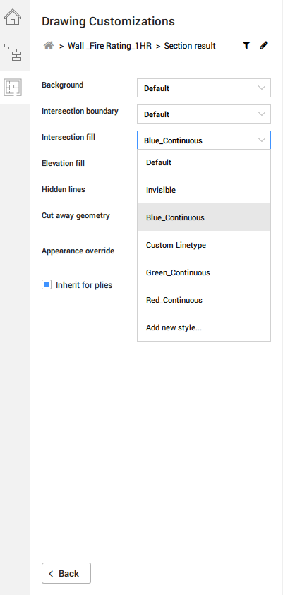
“外观替代”允许您指定实体的填充外观(剖面和高程)的显示方式,以代替在“物理材料”库中已经定义的默认填充图案。当您作为“图纸自定义”模板的一部分在“项目中”类别中创建任何新的“物理材料”条目时,所需的配置独立于图纸项目,而是存储在模板中。以后您可以根据需要将此模板应用于其他项目模型。如果合适,可以通过选中“继承桩”框来进一步确保自定义应用于实体组合中的层。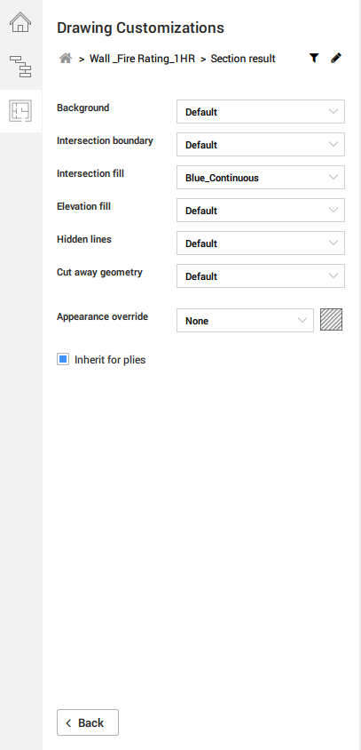
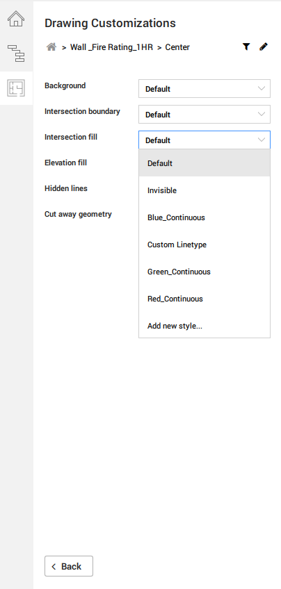
- A similar setup can be found in the Center Customization settings, where your values in the Styles section of the customization template determines the drop-down selections.
Center customization is particularly useful in scenarios where you would like to display the center elements of various planar and/or linear entities. For example, if you were to apply the center customization settings against a planar entity, i.e. a wall, you would be referring to the display behavior of its center plane. However, if you were to apply the same settings against a linear entity, i.e. a beam, you would be adjusting how the beam's center line appears on the sheet.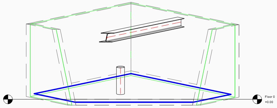
The diagram above illustrates an example of how the center elements differ between planar (wall center plane highlighted in green; slab center plane highlighted in blue) and linear entities (both column and beam center lines in dashed red lines)
There is no default setting to adjust the visibility of these center elements, and they are not normally displayed in section results. - For the Symbol Customization settings, you can find an input dialog to specify your desired external symbol drawing in .dwg format. If you would like to make any further changes to the 2D geometry itself, you can use the Edit button once the dialog is referring to your desired symbol drawing.
Alternatively, you can begin creating one on a default symbol template by hitting the Create New button below the dialog.
You can further apply your saved Styles to specific layers within your external symbol source, thereby allowing you to retain a general symbol drawing across several customization templates with different output results.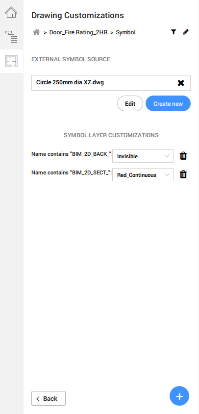
You could also choose not to specify any External Source Symbol, if you already have your desired 2D layers inside the model, usually as a 2D graphical representation that comes alongside the 3D geometry of a Component.
In this instance, simply add a new symbol layer customization value containing part of the desired layer name. If they are part of the default BRX_2D layers, adding "BRX" as a name value will suffice. Drawing Customization will now search within the component entity that the customization template is applied to. This method, however, will not allow any exchanging or sharing of 2D symbols across entities, i.e. replacing a Column with a symbol derived from a BRX layer stored within a (table) 装饰元素。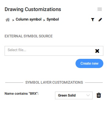
有关BRX层是如何运作的更多信息,请浏览章节步骤:了解BRX_2D层的模板生成图纸文章。
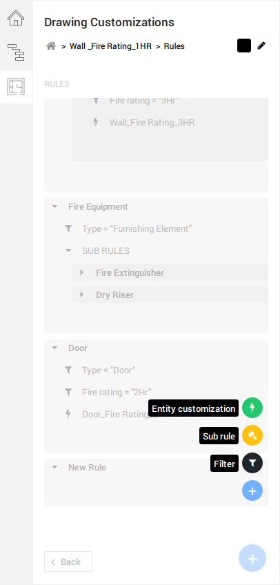
筛选规则
为了能够将正确的自定义样式应用于特定的实体,您必须在“样式”旁边的面板右上角的“漏斗”图标中的“过滤器规则”选项卡中设置适当的过滤器规则,以正确定位这些实体图标。
注意:从V21.1.06开始引入了嵌套属性搜索功能,使您可以指定如何过滤和显示部件中的嵌套对象。
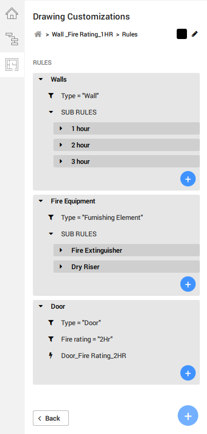
- 筛选规则可以进一步分为子规则,它属于父规则的子集,即。消防设备作为过滤规则,而灭火器则归为子规则。也分别出现在相应的规则级别上。在每个规则的末尾,无论它是子集还是其他子集,都必须以Entity Customization结尾。
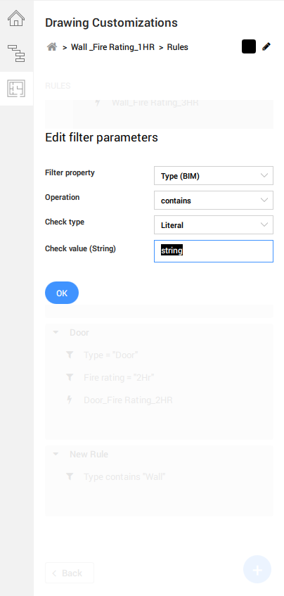
- 添加和编辑过滤器参数将提示您,其中过滤器属性的选项由命名空间设置中导入的BIMPROPERTIES确定。
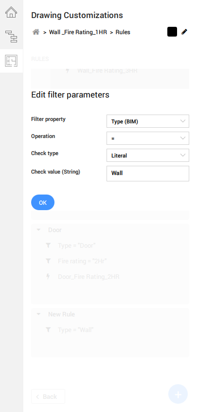
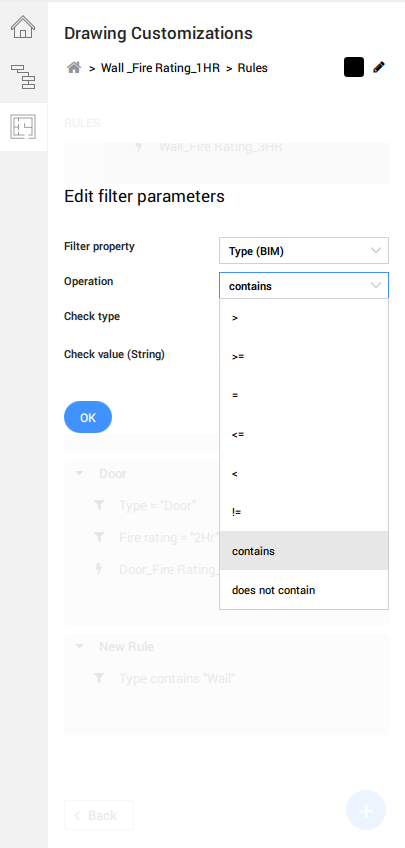
在筛选器操作值也可作为一个下拉。
注意:您也可以开始输入特定的关键字来搜索要过滤的特定属性。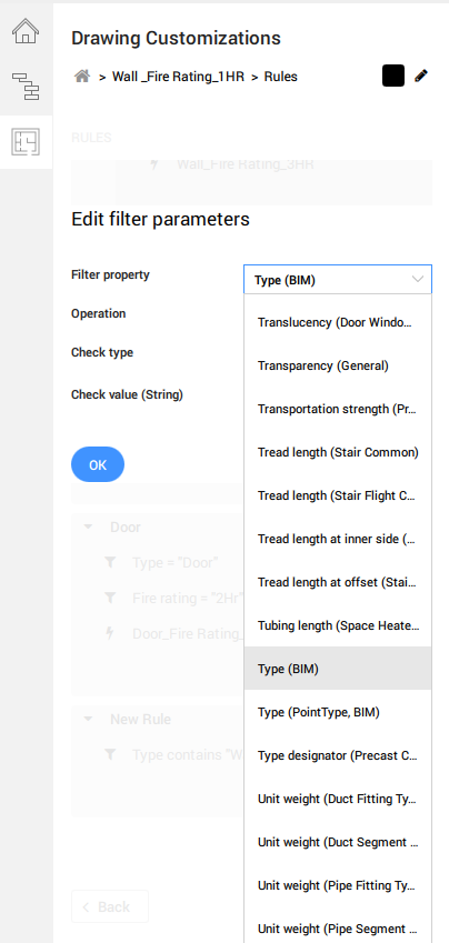
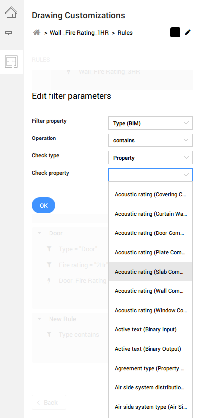
如果您的“检查类型”为Literal,则可以在检查值中手动指定字符串。如果您为“检查类型”选择了“属性”值,则“检查属性”值将引用在“过滤器属性”下拉列表中找到的相同值。
- 要结束过滤器规则并使之合法化,必须添加并填写实体定制值。下拉选择中的可用选项反映了“实体定制”页面中可用的现有定制选项卡。
将模板应用于图纸上的视口
设置完实体自定义项,过滤规则和样式后,您就可以准备图形自定义模板了。
- 要应用模板,请使用所需的视口导航到图纸。
- 打开“属性面板”,然后选择视口以查看其属性。
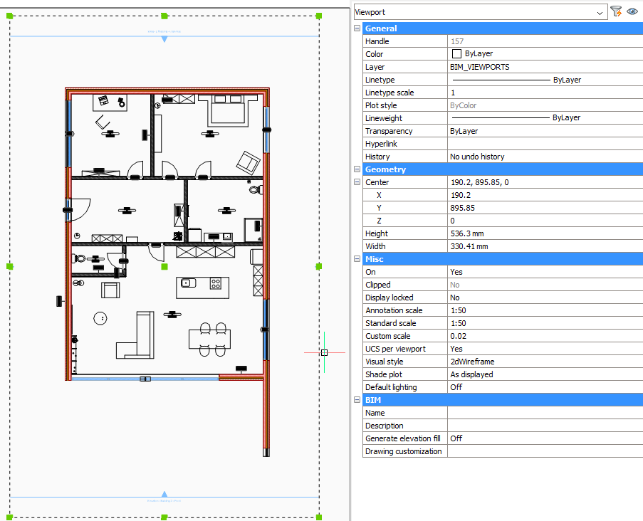
- 导航到“图纸自定义”属性,然后单击右侧的下拉选择。
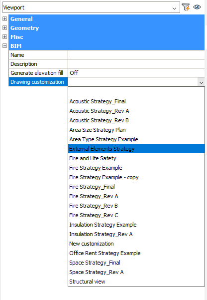
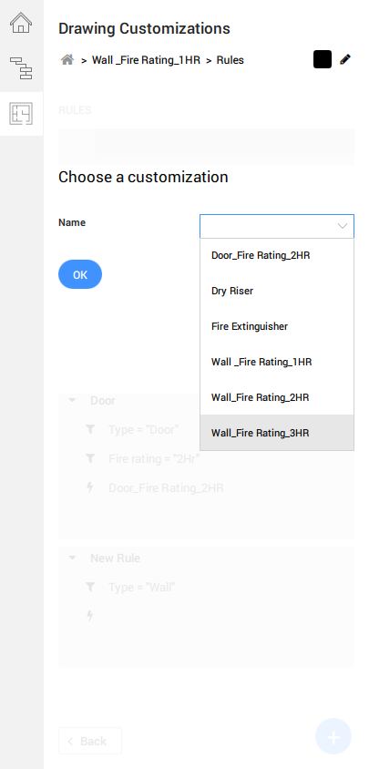
- 选择所需的图形自定义模板。
- 完成后,将鼠标悬停在所选视口上即可访问Quad。单击“模型”选项卡下“四边形”中的“更新部分” 。
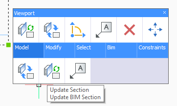
- 根据“图形自定义”设置,应该会看到带有图形更改的刷新的视口。
访问自定义模板
默认情况下,这些模板存储在“支持”文件夹中“自定义”文件夹中的以下路径中,即“ Bim”文件夹下,然后是“节”子文件夹下:
C:\ Users \ <用户名> \ AppData \ Roaming \ Bricsys \ BricsCAD \ V21x64 \ en_US \ Support \ Bim \ Sections \ Customizations
默认情况下,AppData文件夹是隐藏的,因此您可能必须先取消隐藏它。也可以通过在命令行中输入SupportFolder来访问此路径。
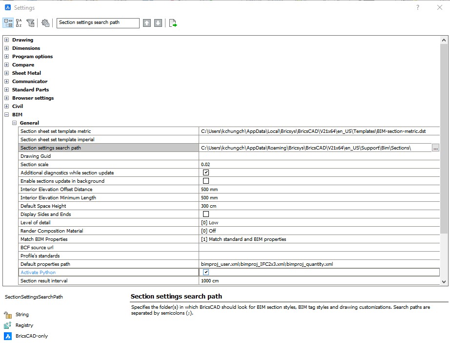
如果您的自定义文件存储在可访问文件夹中的其他位置,则可以指定其他路径。只需在“设置”对话框的“部分设置”搜索路径中重新定义路径,或在命令行中键入SRCHPATH即可:
使用面板创建的新定制将存储在指定路径的“定制”子文件夹中。每个自定义模板都保存为一个单独的文件夹,该文件夹以其基本形式包含Settings.dwg,Filter.json和New customization.json文件。该文件夹还将包含您使用“创建新”按钮创建的所有外部符号源。
Settings.dwg包含在“样式”选项卡中以图层形式创建的值,并且如果您创建了要用作过滤器参数的任何自定义属性,则必须确保它们也反映在Settings.dwg中。

注意:由于这些“自定义”文件夹存储在创建它的计算机中的本地位置,因此,如果您希望与以下计算机上的其他用户共享该文件夹及其内容,则必须将它们及其内容复制并粘贴到其他计算机上的同一位置。其他机器。这是当前的临时过程,因为将在更新中不久发布用于简化“图形定制”工具中共享过程的专用功能。