概述:在本课程中,您将学习如何参数化THCAD BIM实体。
课程目标
完成本课程后,您将能够:
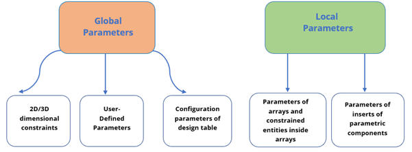
- 了解全局参数和局部参数之间的差异。
- 确定几何和尺寸约束。
- 将表达式设置为参数。
- 参数化您的自定义组件。
- 使用参数控制3D几何形状。
参数化建模
在THCAD中,参数化建模是通过使用几何和尺寸约束来完成的。丰富的工具集使用一组参数来控制2D和3D几何模型。每个参数都将在机械浏览器中显示为一个值。来自不同参数的值可以通过表达式链接在一起。当参数值之一更改时,几何模型将自动更新。该工具集使PCCAD用户可以向任何几何图形添加参数行为,并轻松探索设计意图。
注意:在THCAD中,几何元素之间没有父子关系。例如,如果更改用于创建拉伸3D实体的草图,则不会相应地更改该实体。可以使用参数和表达式创建任何类型的依赖项。
有两种类型的参数:局部参数附加到特定实体。全局参数未附加到特定实体。
处理约束
如果在BIM模型中创建了某些组件(例如,窗户,门等),则可以通过应用3D约束对它们进行参数化。定义约束使您可以控制元素的形状和大小。参数与约束一起通过表达式确定实体的位置。
THCAD中有两种类型的3D约束:一种指定实体的大小,另一种指定实体的位置。
几何约束
几何约束使您可以控制3D实体相对于彼此的位置。

工具栏:参数> 3D约束
四边形:约束
下表显示了3D几何约束。
使固定 |
| 将实体,实体的边或面在工程图中保持在原位。 |
巧合 |
| 在两个边,两个面或两个不同实体的边和面之间应用重合约束。 |
同心 |
| 使两个圆柱,球形或圆锥形表面居中。 |
平行线 |
| 使实体或不同实体的两个面保持平行。 |
垂直 |
| 使实体或不同实体的两个面保持垂直。 |
切线 |
| 保持不同实体的面和曲面相切。 |
刚性套 |
| 使一组实体或子实体成为刚体。 |
尺寸限制
尺寸约束允许您控制图形中3D实体的大小以及它们之间的距离。
工具栏:参数> 3D约束
四边形:约束
功能区:“参数”选项卡> 3D约束
下表显示了尺寸约束。
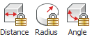
距离 | 在两个子实体之间创建一个距离。 | |
半径 | 为圆柱表面或圆形边缘创建半径。 | |
角度 | 在实体或不同实体的两个面之间创建角度。 |
将表达式设置为参数
在THCAD中,您可以将表达式设置为任何参数,无论是全局还是局部。例如,您可以创建一个仅包含数字或全局参数名称的简单表达式,并将其应用于图形中的相关几何图形。您还可以使用更复杂的公式,包括使用标准运算符和函数。
笔记 |
|
下表显示了可在表达式中使用的运算符。
加法(+) | 产生数值的总和。 |
减或负(-) | 减去两个数值。 |
乘法(*) | 将数值相乘。 |
分配 (/) | 除以两个数值。 |
幂(^) | 计算给定数字的指数值。 |
模或余数运算符(%) | 将一个数值除以另一个后的余数 例如,表达式“ 5%2”的计算结果为1,因为5除以2所得的商为2,余数为1。 |
The following table shows the functions and the syntax which can be used in expressions.
Cosine | cos(expression) |
Sine | sin(expression) |
Tangent | tan(expression) |
Arc cosine | acos(expression) |
Arc sine | asin(expression) |
Cosine | cos(expression) |
Arc tangent | atan(expression) |
Hyperbolic cosine | cosh(expression) |
Hyperbolic sine | sinh(expression) |
Hyperbolic tangent | tanh(expression) |
Arc hyperbolic cosine | acosh(expression) |
Arc hyperbolic sine | asinh(expression) |
Arc hyperbolic tangent | atanh(expression) |
Square root | sqrt(expression) |
Signum function (-1,0,1) | sign(expression) |
Round to nearest integer | round(expression) |
Truncate decimal | trunc(expression) |
Round down | floor(expression) |
Round up | ceil(expression) |
Absolute value | abs(expression) |
Largest element in array | max(expression1;expression2) * |
Smallest element in array | min(expression1;expression2) * |
Degrees to radians | d2r(expression) |
Radians to degrees | r2d(expression) |
Logarithm, base e | ln(expression) |
Logarithm, base | 10 log(expression) |
Exponent, base e | exp(expression) |
Exponent, base 10 | exp10(expression) |
Power function | pow |
Random decimal, 0-1 | Random(expression1;expression2) * |
*Use the list separator character as defined on your system: , (comma) or ; (semicolon).
Parametric Blocks
Parametric Blocks refer to blocks that have parameters that determine the size and shape of the 3D geometry. Once the parametric block is created, it can be inserted as a block reference in the drawing. The parameters of your block can be changed after you insert it in your model. Thus, no need to modify the parametric block file individually. The parametric blocks also enable you to use the same block in different sizes and in different shapes in your model.
Procedure: Parametrizing a custom component
The window that was created in the previous lesson is used to demonstrate how the parametric design works. This window consists of three solids: subtractor, fixed frame, and glass pane.
Step 1: Before starting to add constraints:
- Open the Mechanical Browser with the MechanicalBrowserOpen command, to control and manage the values of 3D constraints and parameters.
Note: The Mechanical Browser allows to navigate through all the constraints and parameters in the drawing and to edit dimensional constraints.
- Make sure that the Enable selection of 3D solid faces (
 ) is toggled on in the Selection Modes To easily follow the steps, make sure Boundary Detection is toggled off.
Step 2: Applying fix constraints
Command: DmFix3d
- Turn on the BIM_Subtract layer.
- Select the entities (1) you want to add a fixation to.
(Optional) Press the TAB key to select obscured geometry.
- Choose Add Fixation (2) in the 3D constraints command group in the Quad.

The fixation appears in Mechanical Browser as ‘ Fix_1’.

Step 3: Applying rigid constraints
Command: DmRigidSet3d
- Select the entities to apply the Rigid Set constraints.
The entities remain in the same position with respect to each other when they are in a Rigid Set.
To select more than one sub-entity of the same type at a time, take the following steps:- Use Look From Widget (4), by default it is at the top right of your screen, to change the view from 3D to TOP.
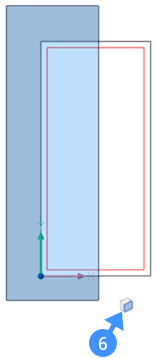
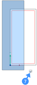
- 使用选择框(5)选择实体。绘制选择框时,按CTRL键可更改子实体选择的类型。每次按CTRL键,子实体选择的类型都会改变。可以在您的鼠标光标下看到子实体的类型,例如,面(6)或边(7)。
注意:默认情况下,选择框会看到并选择实体。

 在四边形的3D约束命令组中,选择“添加刚性集”()。
- 对另一侧重复相同的过程:顶部,底部和右侧。
步骤4:应用距离约束
命令:DmDistance3d
窗口的尺寸和玻璃板的厚度。
- 关闭BIM_Subtract层。
- 选择第一张脸。
脸部突出。
- 将鼠标悬停在第二张脸上。
按下TAB键以突出显示被遮盖的脸。
- 当第二个面突出显示时,在四边形的3D约束命令组中选择“添加距离”(8)。

提示您:指定距离值或[几何驱动] <xxx.xx>:
- 请执行以下任一操作:
- 按Enter键或右键单击以接受当前值。
动态尺寸(DYN)处于活动状态时,当前值将显示在动态尺寸字段(9)中。
- 在命令行中输入一个值。
- 按Enter键或右键单击以接受当前值。
- 两个曲面之间的距离值出现在“机械浏览器”中。
注意:要删除模型中的任何约束,请在“机械浏览器”中选择约束,例如,固定,刚性集…,然后按Delete键或右键单击并选择Delete选项。
步骤5:应用参数
我们将创建一个控制窗口宽度的参数。
- 在机械浏览器中右键单击文件名(10)。
- 在上下文菜单中选择“添加新参数(11)”。
将创建参数设置网格,并将该参数添加为“ v1 = 1”(12)在Mechanical浏览器中。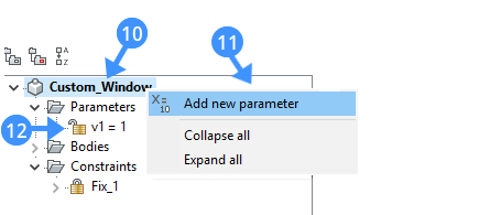
- 选择参数,然后在设置网格中编辑其属性。
下图显示了自定义窗口的Width参数的属性。下表演示了每个属性。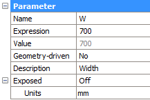
姓名
输入参数名称。 表达
键入一个值或公式。 价值
显示参数的当前值。 几何驱动
如果是,则将参数设置为geometry-driven。 描述
定义参数的可选描述。 裸露
控制在将组件插入模型中时参数在属性面板中是否可用。 单位
指定参数是线性的,面积的还是体积的。
- 要将刚创建的参数与尺寸约束链接在一起,请在“机械浏览器”中选择距离约束,然后使用这些参数在约束设置网格的“表达式”字段中公式化表达式。
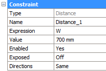
- (可选)更改参数的表达式值,然后按Enter。分配的距离约束将相应更改。
*在图形中,您可以设计尽可能多的约束。请注意,该软件将使您避免施加不必要的约束。