命令: BimApplyProfile,BimLinearSolid,BimStructuralConnect,BimAddEccentricity,BimRecalculateAxis,拖动,BimStretch
概述:在本课程中,您将学习如何将钢结构型材插入工程图中以及如何进行连接。
课程目标
完成本课程后,您将能够:
- 将配置文件插入您的BIM模型
- 将轮廓应用到模型中的现有线或实体
- 将不同的配置文件彼此连接
- 更改配置文件的位置而不会失去它们的连接
- 更改轮廓轴的位置
教程:如何使用结构钢建模工具
点击这里观看
如何使用BIM配置文件面板

注意:PCCAD不会自动生成不同线段之间的连接,因为选择的轮廓是结构钢。
关于BimStructuralConnect
所述BimStructuralConnect命令自动生成简档连接。

有关此命令的更多信息,请访问“命令参考”文章BimStructuralConnect。
教程:如何连接线性实体
点击这里观看
与线性实体建立结构连接
选择您要连接的配置文件。
启动BimStructuralConnect命令。通过在命令栏中键入它或在Quad的“模型”选项卡中选择“ StructureConnect”。
启用热键助手(状态栏上的HKA)时,屏幕上将显示一个小部件(如下所示)。点击CTRL键以循环浏览不同的选项。
按Enter接受所选的选项并结束命令。
关于拖动
使用“拖动”命令可以更改绘制轮廓的一个段,而不会丢失与其他段的连接。

有关此命令的更多信息,请访问“命令参考”文章Drag。
更改线段的位置
注意:仅当使用BimStructuralConnect命令创建连接时,此方法才有效。
确保已启用面部检测。可以通过键入DisplaySidesAndEnds并按1来完成。
选择一个垂直于纵断面截面的面。
启动拖动命令。
Click the mouse to set a new position for the segment. Or use the dynamic dimension field to enter a value for the displacement.
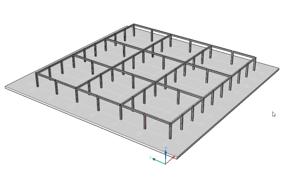
Procedure: Use modeling tools to create a structural steel model
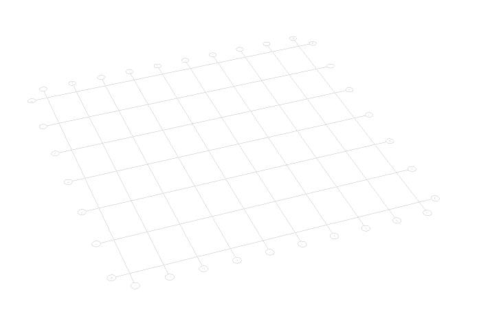
Draw a BimGrid as a base.
Launch the BimGrid command.
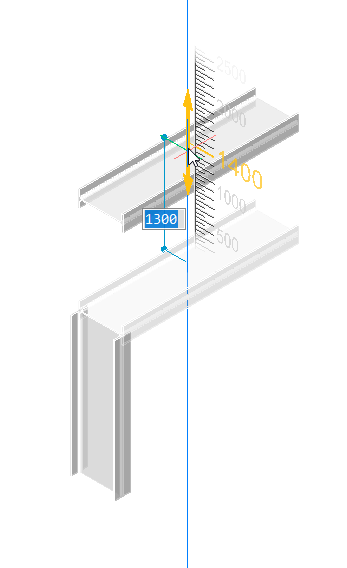
Click a starting point and enter values into the dynamic dimension fields.
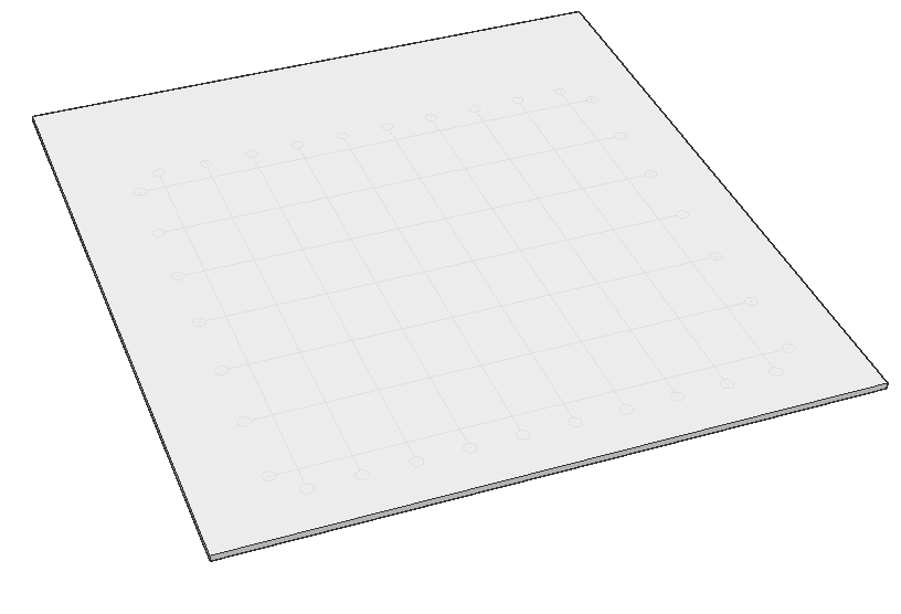
Draw a base slab underneath the grid.
Create a slab using the Box command.
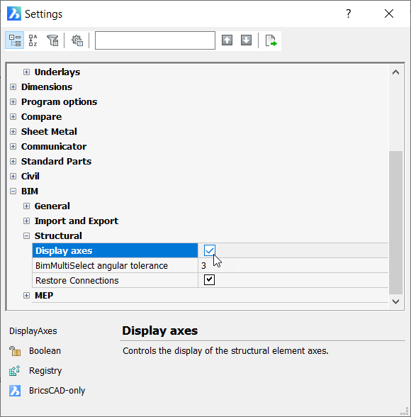
Ensure that the grid is entirely on top of the slab and that the axes of your profiles are displayed.
Go to the Settings dialog and under the BIM > Structural section. Ensure that 'Display Axes' is checked.
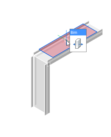
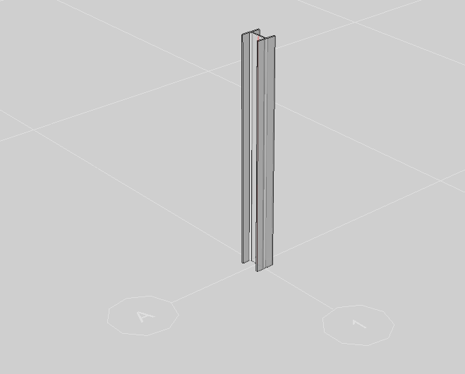
Open the Profiles Panel and drag a structural steel profile into your model. Start drawing at the intersection point of two grid axes and draw vertically upward.
Note: To snap specific points, make sure you have toggled on the different types of points you want to snap in the context menu when right-clicking on ESNAP.
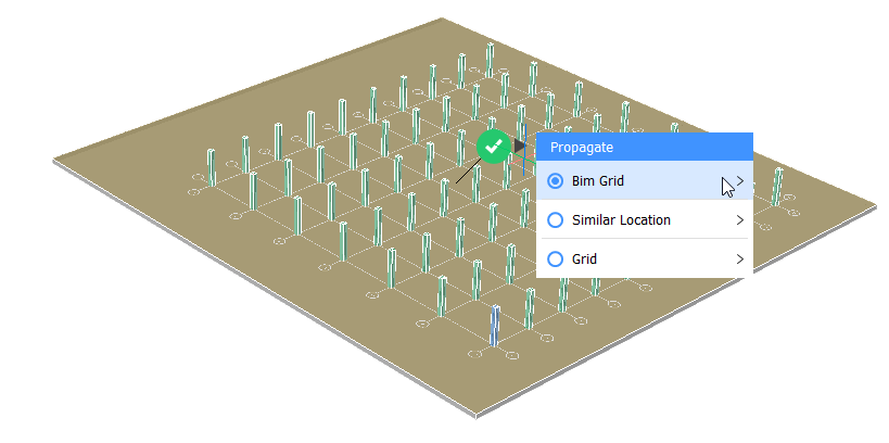
Launch the Propagate command.
Select the slab as base solid and press Enter.
Select the column as your detail element and press Enter. BricsCAD will zoom into the 3D detail. Press C to copy the column as a solid, not as a block.
Note: The default setting for Propagate is to copy the object as a block.
Hit Enter.
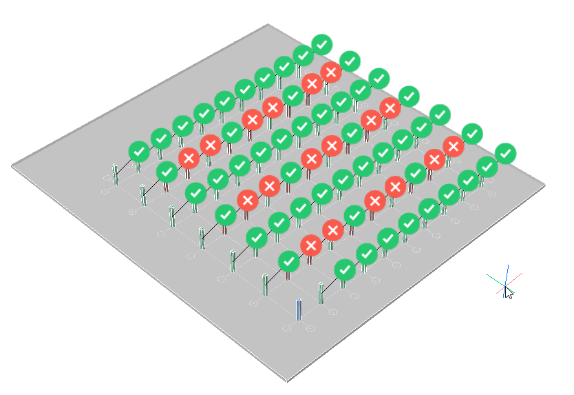
注意: BricsCAD会自动将光束复制到每个网格相交处。这是因为您选择了以BimGrid作为基础实体的楼板。
将鼠标悬停在绿色的选中标记上,然后在对话框中单击BimGrid。
单击爆炸。现在,您可以手动切换单个建议以创建您选择的模式。
按Enter接受并结束命令。
在列之间创建梁。
打开“型材面板”,然后将结构钢型材拖动到模型中。要设置起点和终点,请单击列的顶部,然后单击下一个。双向执行此操作。
注意:如果要旋转轮廓以使法兰朝上,请按Q(从四分之一圈开始)。轮廓将绕其轴旋转90度。
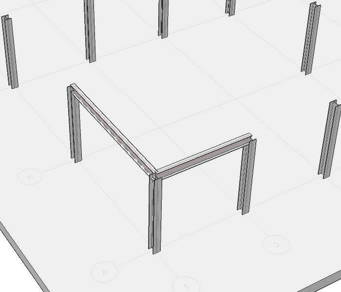
将梁截面从“纵断面面板”拖放到该梁上。给第二个光束较大的轮廓,因为它具有更长的跨度。
选择一个梁并启动BimAddEccentricity命令以更改梁轴的相对位置。
单击向下箭头。光束相对于其轴线向下移动。
按Enter结束命令。
对另一个光束重复步骤3-5。
选择该列和两个梁,然后启动BimStructuralConnect命令以进行简单连接。按Enter接受默认选项。
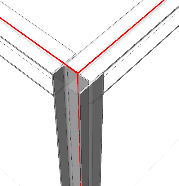
对其他2个结点重复步骤7。
Select the two columns connected to the beam in the Y-direction and launch the Propagate command.
Select the beam in the Y-direction as the detail solid.
Press C to copy it as a solid, not as a block.
Press Enter.
Choose which suggestions to accept. Hit Enter to accept and finish the command.
Note: Suggestions are made at the bottom of every column because the situation is symmetrical.
You can toggle the suggestions off.
Repeat steps 9 - 13 to create beams on the X-direction.
Note: You can use box selections to select all the lower beams at once.
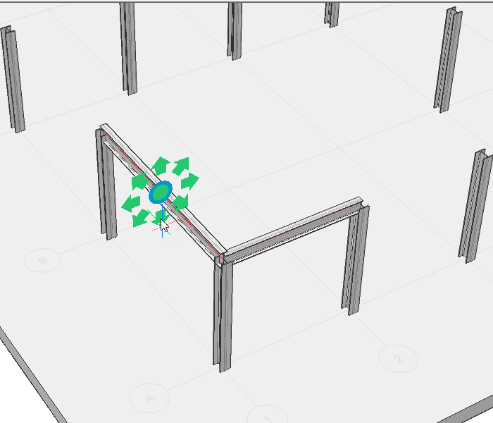
Move a Beam
Ensure that face detection is toggled on. This can be done by typing DisplaySidesAndEnds in the commandline and pressing 1.
突出显示所需列的侧面,然后启动“拖动”命令。
将列移动到所需位置。
注意:保持与相邻梁的连接。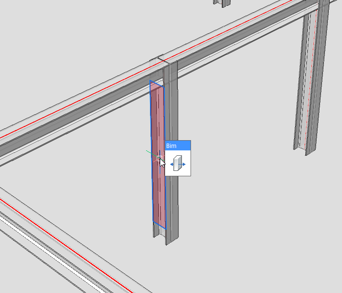
过程:使用建模工具创建更详细的连接
确保面部检测功能已关闭。可以通过键入DisplaySidesAndEnds并按0来完成。
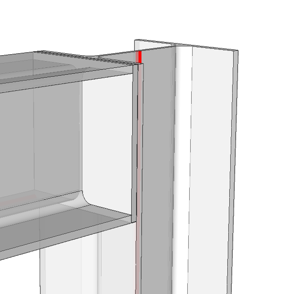
启动Box命令并将鼠标悬停在列的侧面。
按下Shift键一次,使脸部突出显示为蓝色。
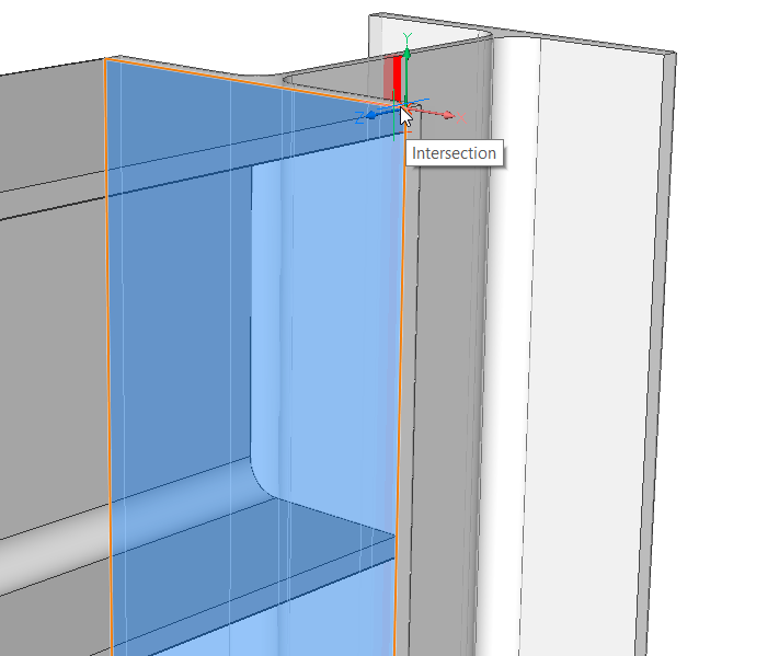
- 现在在色谱柱的法兰上画一个板。
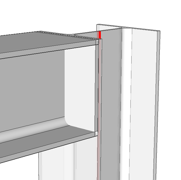
选择梁并启动“减法”命令。
选择端板,然后按Enter。
选择该面,然后从四边形启动Bimify命令。
注意:您还可以通过在“边界”选项卡中四选“手动分类”来手动分类板。
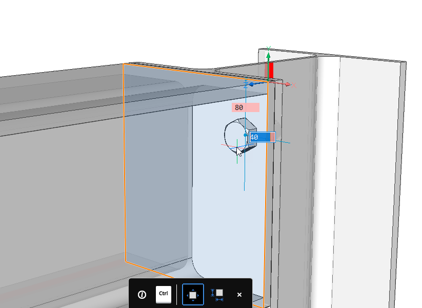
打开库面板,然后将螺栓拖到板上。
注意:您可以通过在动态尺寸字段中输入值来精确定位。
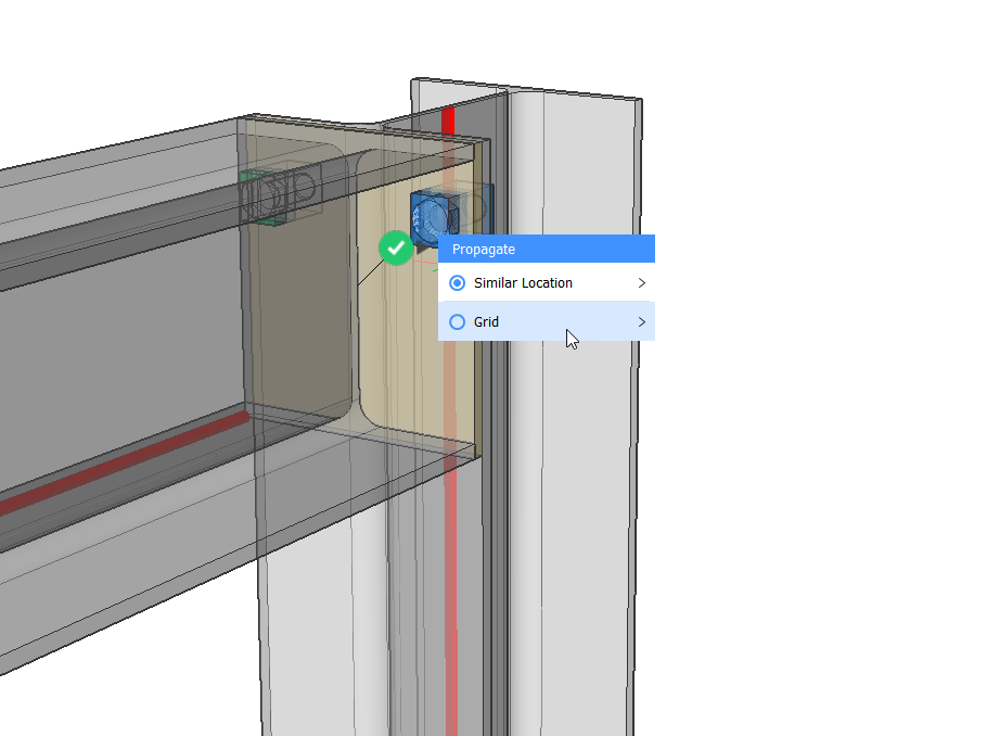
选择板并启动传播命令。
选择螺栓作为详细信息,然后按Enter。
再次按Enter,然后单击蓝色问号。它将变成一个绿色的选中标记。
将鼠标悬停在复选标记上,然后选择网格。
添加一行。
按Enter结束命令。
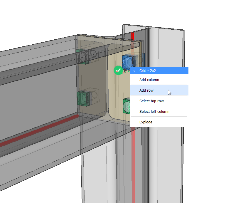
现在已经创建了详细的连接。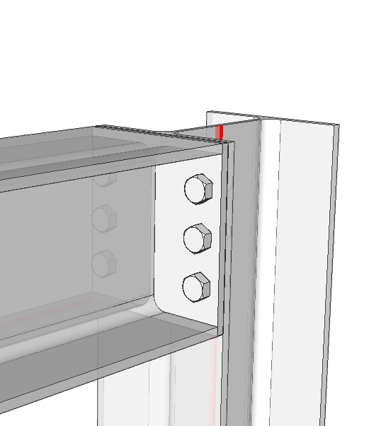
过程:使用BimStretch修改结构钢
- 打开一个新工程图。
- Open the Profiles Panel by clicking on it on the right-hand side of your screen.
Note: If the Profiles Panel icon isn’t visible yet, right-click on the ribbon and check Profiles in the context menu under - Drag the profile you want to draw a structure with within the model space.
- Draw a column with a height of 3000 mm. Don’t exit the command and draw a connecting beam with a length of 5000 mm horizontally. Now, add another column at the end of the beam. The height of this column is also 3000 mm.
Note: Make sure you turned the profiles in the right way.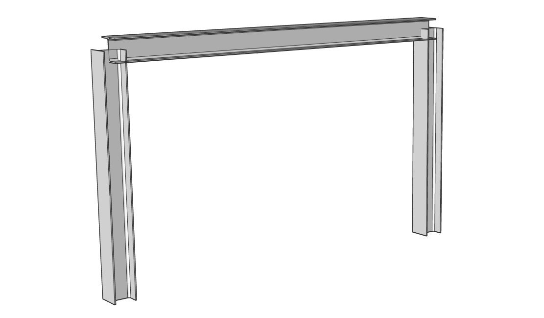
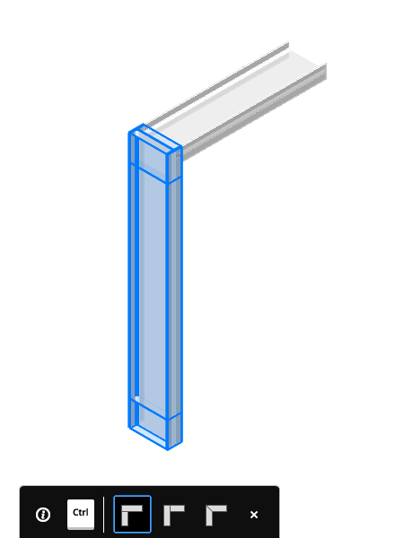
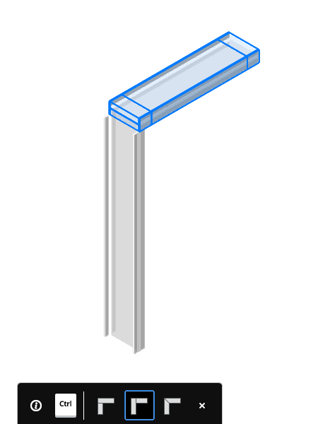
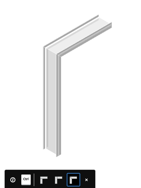
选择3个梁,然后在功能区中选择“连接结构”,或从“四边形”中选择命令。您将能够选择自己喜欢的连接。选择L连接选项,然后按Enter键。您的实体现在已连接。
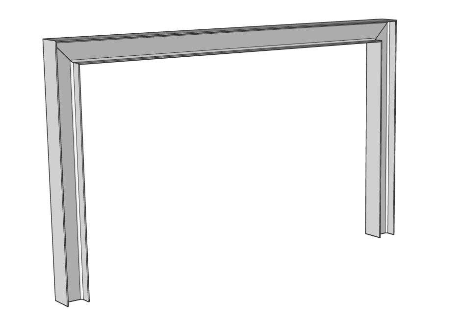
在功能区中,确保启用“显示侧面和末端”和“优先选择面”。可以在“结构/ MEP”选项卡中找到它们。
检查配置文件是否正确分类为“梁”和“列”。
启动Multislice命令并在中间对光束进行切片。
系统将提示您:沿轴切片?按Enter接受默认选项(是)。- 选择梁的中点,然后按Enter。现在,您的光束被切成两束。
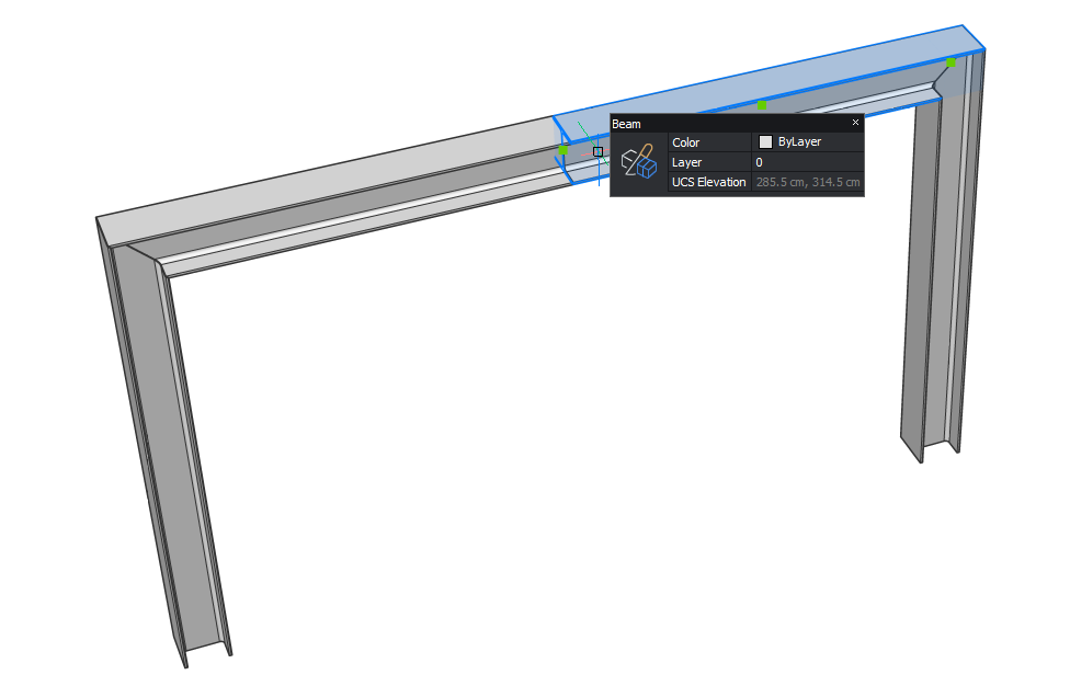
- 在结构的中间选择梁的2个末端。它们将以黄色突出显示。
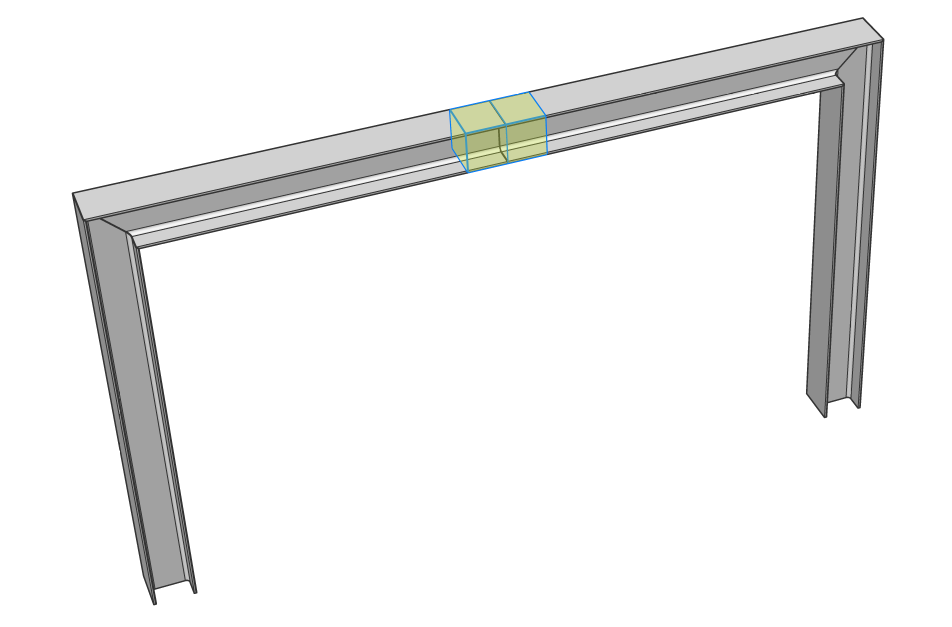
- 在模型选项卡中,四合选择BimStretch命令。
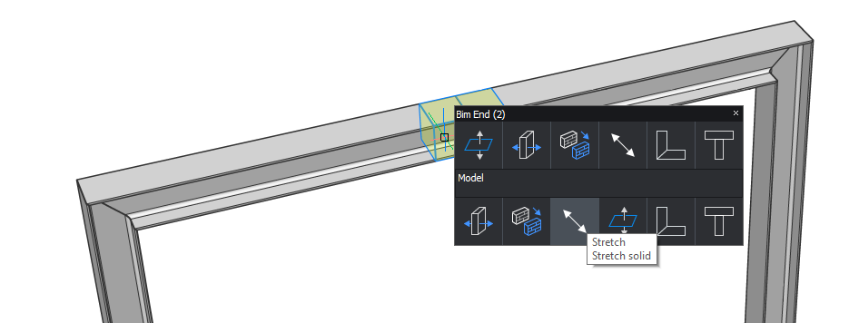
- 垂直向上悬停,输入2000 mm的高度,然后按Enter键接受。
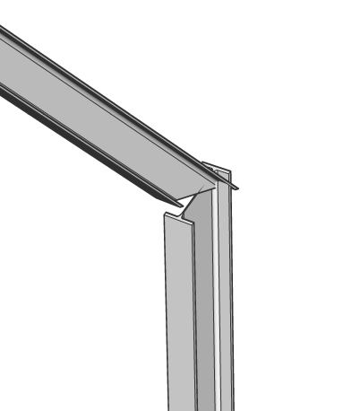
- 结果应如下所示。
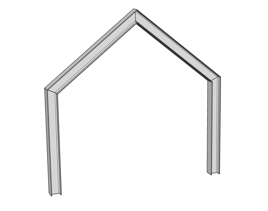 如您所见,轮廓之间的连接会自动适应实体之间的新角度。
注意:如果您只选择了梁中间的两个侧端之一,则未选中侧的连接将不包括在拉伸中,如下所示: