...
- 使用现有的2D平面创建墙。
- 在两堵墙之间建立连接。
- 将墙壁连接到其他元素。
教程:如何创建墙
有两种创建简单墙的方法:使用PolySolid工具或使用BimQuickdraw。有关Quickdraw的详细说明,请阅读文章BimQuickDraw和使用BIM Quickdraw。
关于Polysolid工具
使用“ Polysolid”工具,您可以通过选择起点,终点并输入高度来创建墙体。请注意,在PCCAD Polysolid”工具,您可以通过选择起点,终点并输入高度来创建墙体。请注意,在THCAD BIM中,始终始终首先创建几何图形,然后再添加材料或合成。这样,在对初步设计进行建模时,无需担心细节。
建议使用动态尺寸和极坐标跟踪。动态尺寸可以用于指定墙的长度,而Polar Tracking可以控制方向。

![]()
有关此命令的更多信息,请访问“命令参考”文章PolySolid。
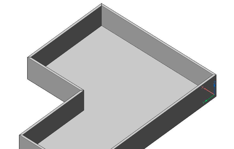
过程:创建一个简单的墙
启动Polysolid工具。
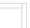
选择一个起点,将自动显示墙的足迹(1)。
在所需方向上移动光标,当前长度值将显示在长度动态输入字段(2)中。
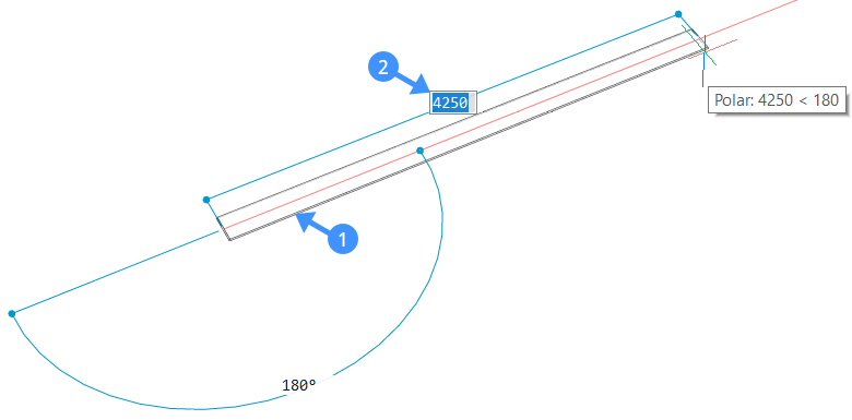

选择一个端点或在动态输入字段中输入一个值,然后按Enter键。显示相邻墙的足迹(3)。选择一个新端点或在动态输入字段中输入值以创建相邻的墙段。
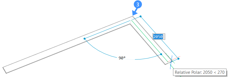

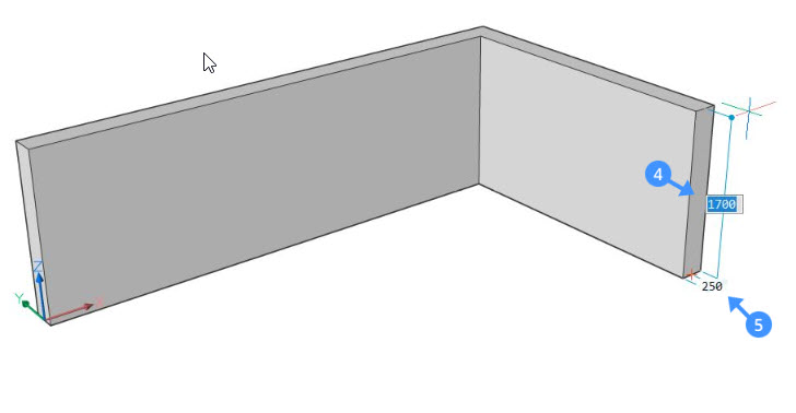
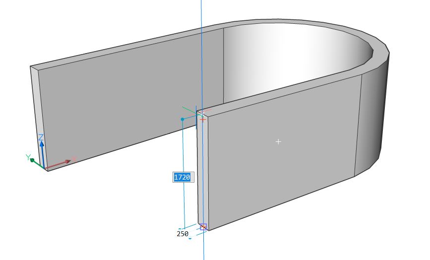
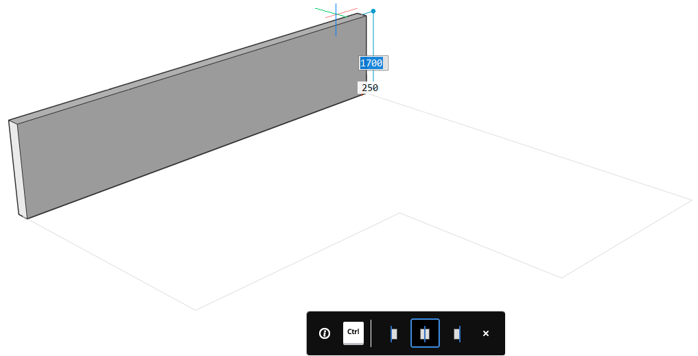
再按一次Enter键或单击鼠标右键。墙壁的高度会在高度字段(4)中动态显示。在这里,您可以更改墙的默认高度。要更改墙的宽度,请使用宽度字段(5)。您可以通过按Tab键在两个动态输入字段之间切换。

- To change the justification of the wall hit CTRL while the ’Polysolid justification Hotkey Assistant widget‘ appears at the bottom of the screen.


Note The width and height of the previous wall will be the new default values of the next Polysolid.
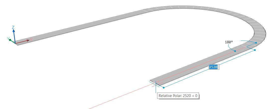
Procedure: Creating a curved wall
Launch the Polysolid tool.
Select a start point and move the cursor to set the length or click to set the endpoint.
To create a curved wall, type A and press Enter to choose Draw arcs or select Draw arcs in the prompts menu.
Now move the cursor in the desired direction to curve the wall. Enter a value in the dynamic input field to set the degree and length of the arc. Press Enter.
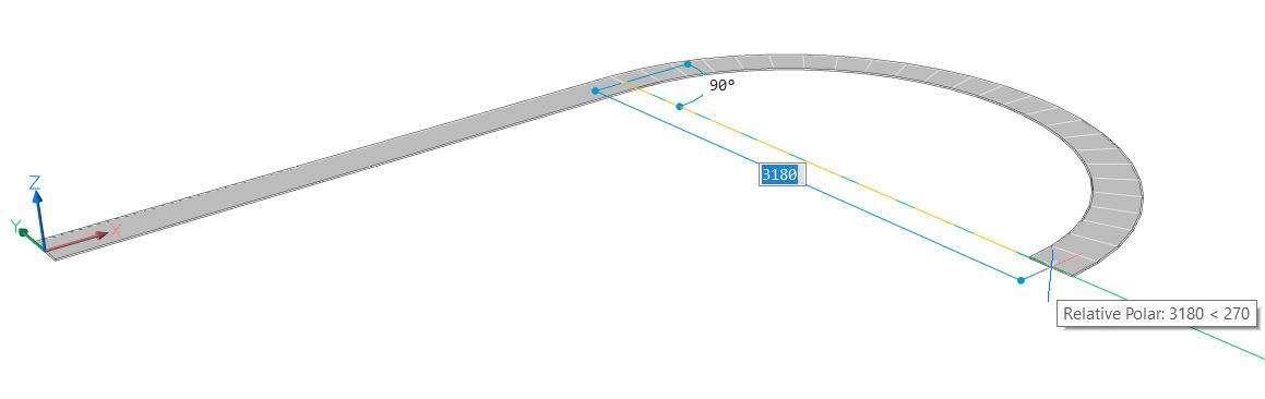

您可以通过单击或在动态输入字段中输入值来继续创建弯曲的相邻墙段。要返回绘制直线墙段,请键入L并按Enter或在选项对话框中选择“绘制线”。

- 再按一次Enter键或单击鼠标右键。墙的高度在高度字段中动态显示。键入一个值以更改墙的默认高度。要更改墙的宽度,请使用width字段。您可以通过按Tab键在两个动态输入字段之间切换。

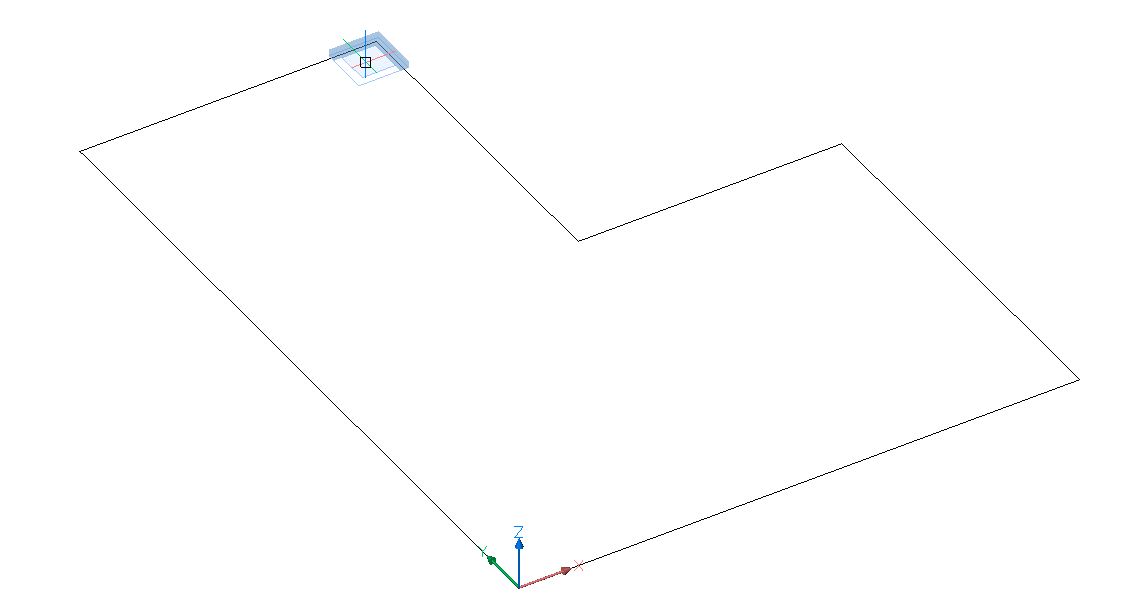
过程:使用现有的2D平面创建墙
使用现有的2D平面视图,您可以在3D中创建墙元素。
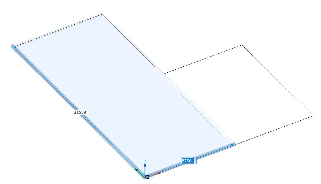
单击四边形中的Polysolid工具,然后在命令行上键入E,或在提示菜单中选择“实体”。通过在Polysolid中使用“实体”选项,您可以从2D布局创建3D几何。
选择一个2D线性实体,它将是Polysolid基础。
线,开放和闭合折线,圆弧,圆,椭圆,椭圆弧和样条线都可以作为多实体基础。
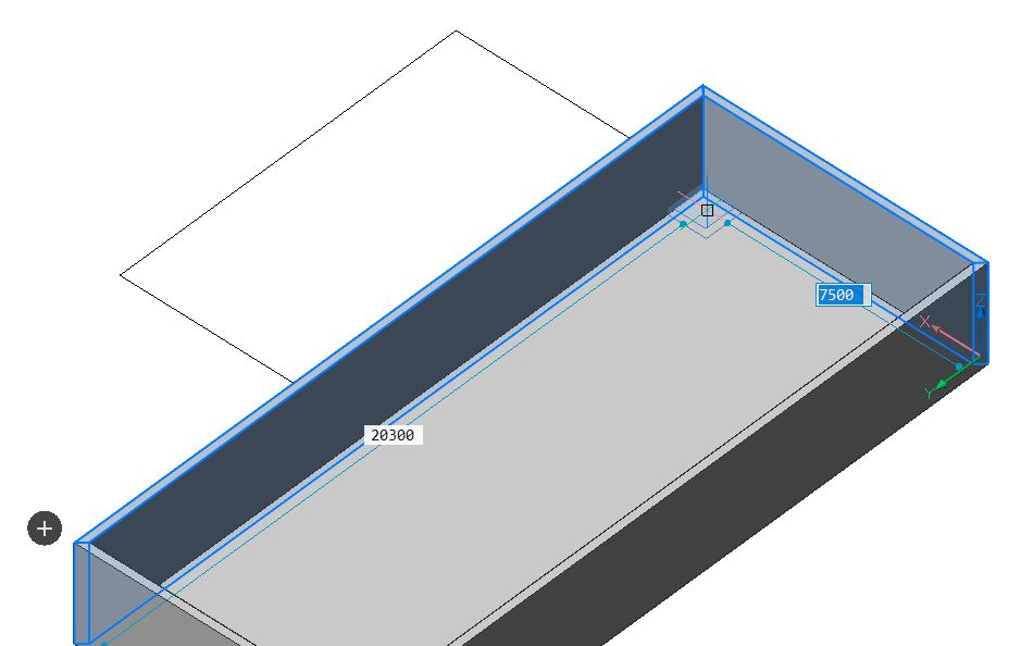
上下移动实体,然后单击鼠标左键以设置墙的高度,在动态输入字段中输入一个值,或右键单击以接受默认值。
墙的当前宽度出现在“宽度”字段中。在“高度”和“宽度”字段之间按Tab键切换。
出现“热键助手”,并显示可能的对齐选项。按CTRL键可遍历墙对齐方式选项。

也可以使用现有的2D平面图通过BimQuickDraw工具创建墙:
从Quad中打开Quickdraw工具,或在命令行中键入Quickdraw。
光标会自动捕捉到2D工程图的线条。将光标放在要放置第一个角的位置,然后单击鼠标左键。

将鼠标悬停在对角,然后再次单击鼠标左键,或者在相应的字段中键入边的长度值,然后按Enter键。

The Quickdraw tool always uses the default height and width settings.
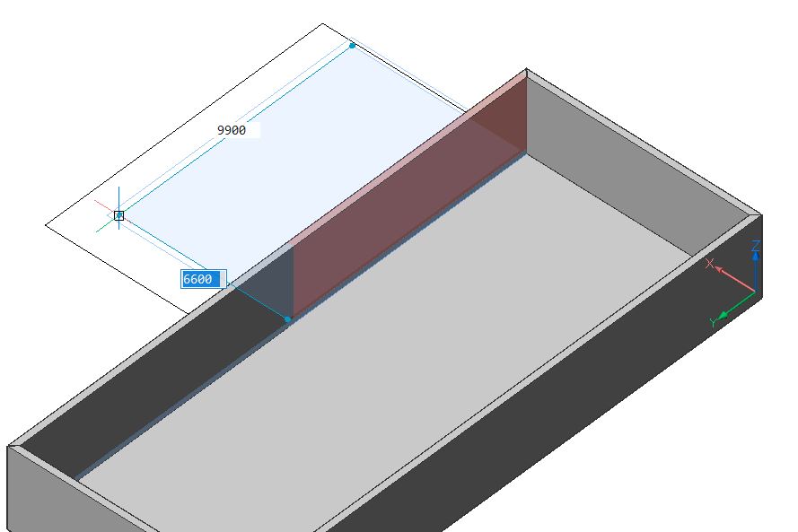
To change these values type S and press Enter to open the Quickdraw Settings. Change the values in this menu.To finish the L-shaped form, you can draw a new rectangular on the second part of the figure. The common wall of the two rectangles will automatically be removed if you draw a second rectangular starting from the interior side of the first rectangular as indicated below:

While drawing the second rectangular, you can see the wall that will be deleted is displayed in red.


For more info about Quickdraw, please read the article Using BIM Quickdraw.
About the BimConnect Tool
The BimConnect tool allows you to connect one wall to another element.

![]()
For more information about this command, visit the Command Reference article LConnect.
Procedure: Connecting two walls
Tutorial: How to connect walls
to watch
Select two wall elements and apply the LConnect tool.
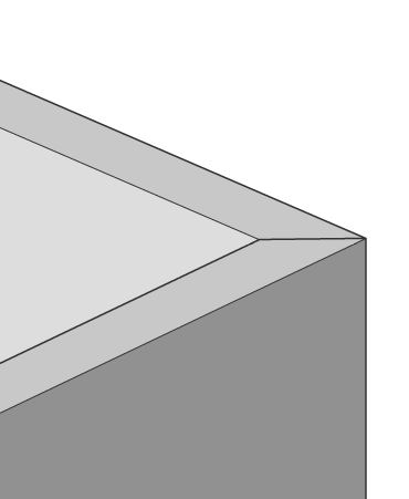
When two walls intersect, a mitered connection will be created by default.


Change the layout of the wall connections using the ‘LConnect HotKeyAssistant widget’.
The selected connection type is indicated by a blue frame.
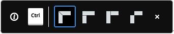

The connection can be (from left to right) a bisector L-connection , L parallel type 1 , L parallel type 2 or a disconnection.
...
- Bisector L-connection (miter)
When the bisector L-connection is selected, the walls are connected at an angle of 45°.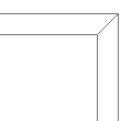

- 并联L型连接1并联L型连接2
选择L并联类型1或类型2连接时,墙壁以90°的角度连接。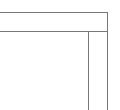


- 断开
连接选择“断开连接”选项时,将删除墙之间的现有连接。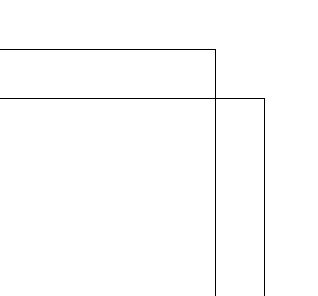

按Enter键接受当前的连接类型,或按CTRL键循环显示可能的连接选项。
将墙连接到其他元素
“与最近的连接”工具使您可以将墙的次面连接到另一个元素的主面,而不必考虑面的方向。该工具可用于将墙壁的顶面连接到屋顶,将底面连接到楼板或将楼板的侧面连接到墙。
...
注意:使用“最近连接”工具之前,请确保在选择模式设置中启用了“选择面”选项。

![]()
有关此命令的更多信息,请访问“命令参考”文章TConnect。
过程:在两堵墙之间创建T型连接
在绘图区域中,突出显示要连接到另一面墙的面。
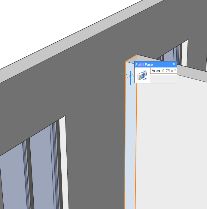

使用四边形中的“与最近的连接”工具。
“最接近的连接”工具通过将第一面墙的面拉伸到另一面墙的面来自动在两面墙之间建立T型连接。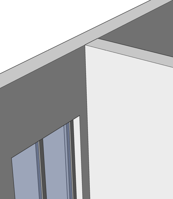

关于“选择对齐的面”工具
“与最近的连接”工具也可以用于将墙的多个面连接到另一个元素的最近面。为此,请使用“选择对齐的面”工具。使用此工具可以突出显示与当前选择共面的所有面。

![]()
有关此命令的更多信息,请访问“命令参考”文章SelectAlignedFaces。
步骤:将墙壁的多个面连接到屋顶板上
- 要选择与当前选择对齐的所有面,请高亮显示其中一面墙的顶面,然后单击“四边形”的“选择”选项卡中的“选择对齐的面”工具。
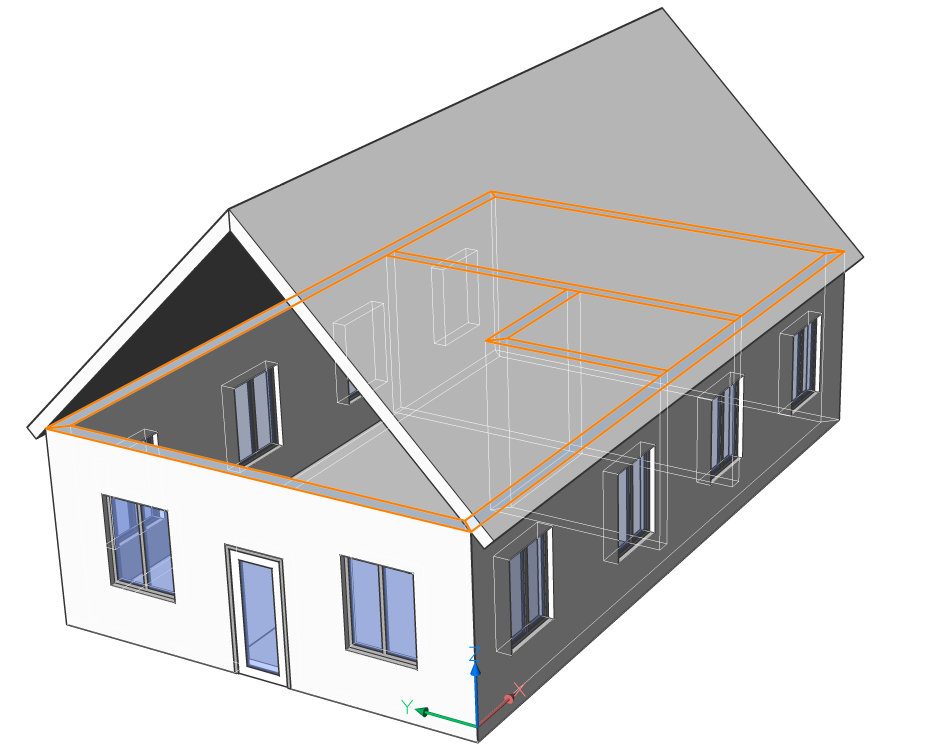

- 启动“使用最近的连接”工具。墙壁的顶面连接到屋顶。