...
选择要连接的网段,然后启动BimFlowConnect命令。
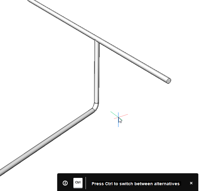
打开热键助手(状态栏上的HKA)时,屏幕上会出现以下窗口小部件,按CTRL键可在不同选项之间循环。


通过按Enter结束命令,现在已经连接了网段。
...
过程:更改分段的位置
在开始过程之前:启用对边和边的选择:

![]()
- 单击BIM工具栏上的图标。
- 键入DisplaySidesAndEnds,然后键入1或ON。
...
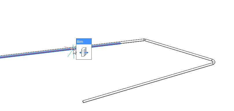
使用“拖动”命令可以更改绘制轮廓的一个片段,而不会失去其与其他片段的连接。

![]()
有关此命令的更多信息,请访问“命令参考”文章Drag。
- 将鼠标悬停在线段上,选择一个垂直于纵断面截面的面。
- 启动拖动命令。
- 为该段选择一个新位置,或使用动态尺寸字段输入位移值。
注意:软件会自动重新生成网段之间的连接。
机械手
- 将鼠标悬停在线段上,选择一个垂直于纵断面截面的面。
- 选择“操作”。
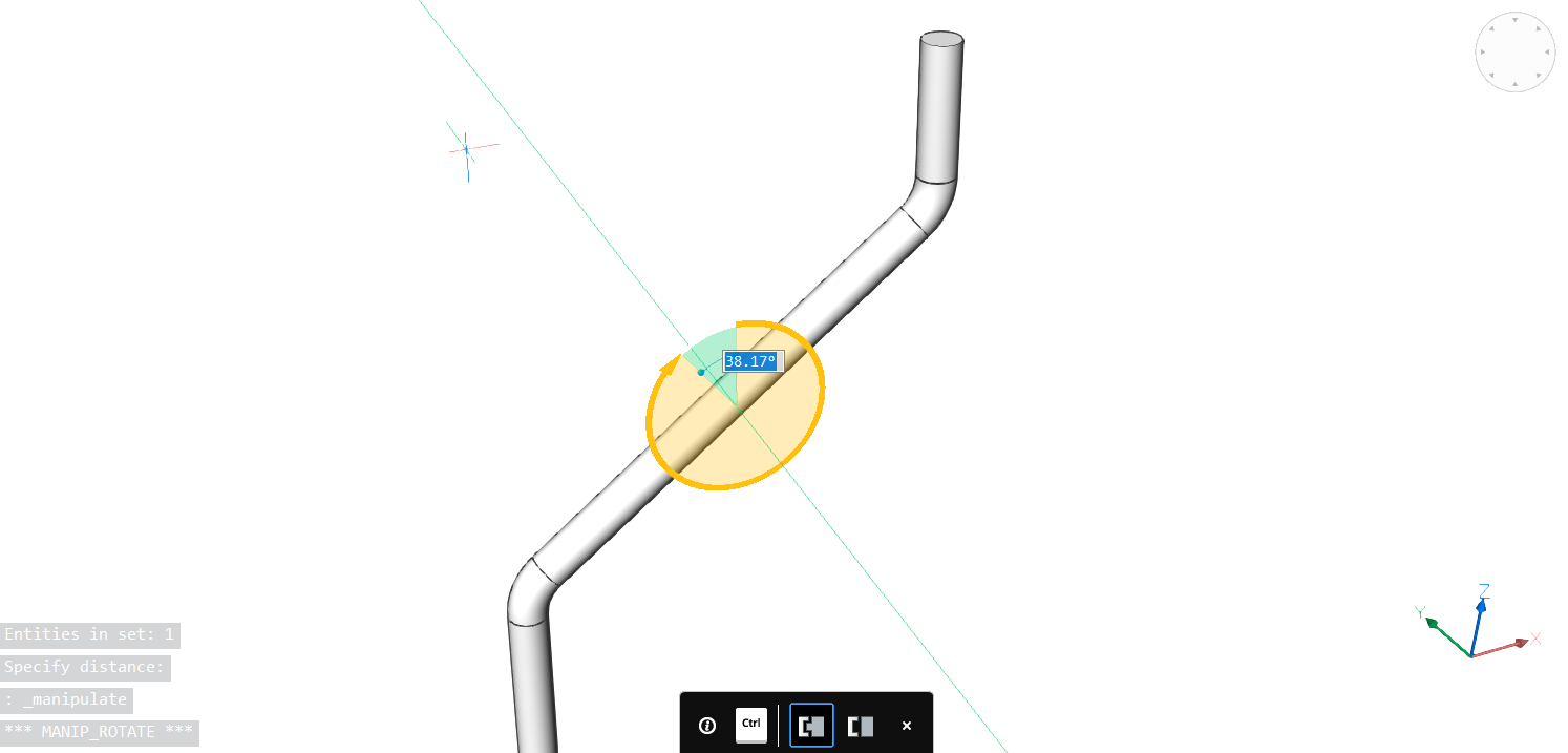
- 为该段选择一个新位置,或使用动态尺寸字段输入旋转值。
- 单击新位置或输入旋转角度,然后按Enter。
过程:使用MEP建模工具绘制和连接轮廓
打开包含MEP模型的工程图。您可以在本文末尾下载包含图纸的MEP.zip文件。

打开屏幕右侧的BIM配置文件面板(请参阅可停靠面板)。
在HVAC上进行过滤,然后选择“ 12“ x 8”矩形”轮廓,将其拖动到模型空间。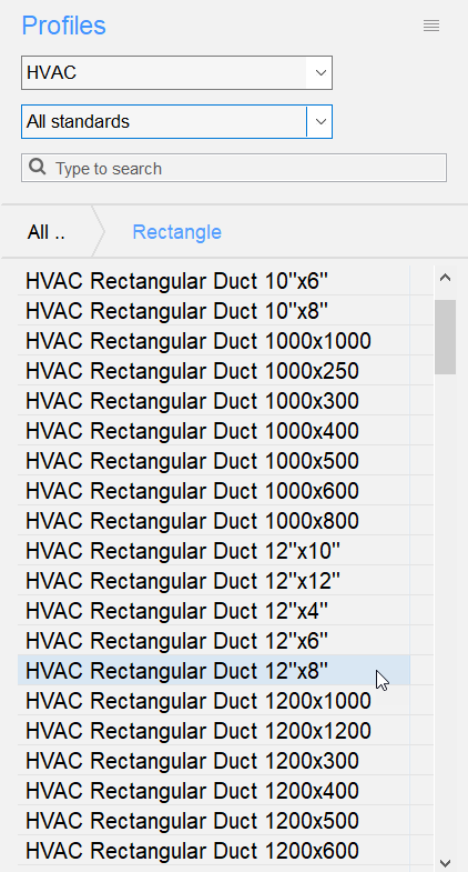

定义轮廓的起点。
捕捉到黄色矩形的几何中心。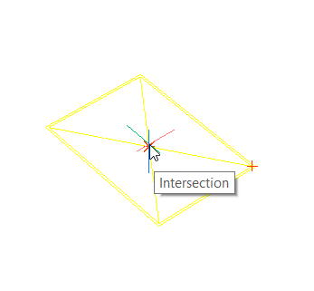

Turn Ortho on and define the next points of the profiles by using the dynamic dimension field.
Quarter turn the profile by entering Q in the commandline.
Go up 3.5, go 3.5 to the left and go 21 horizontally.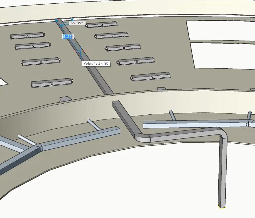
Connect the other rectangular ducts on the side to the one we have just created.
Select the ducts together with the main duct and launch the BimFlowConnect command. Your connection should look like the image below.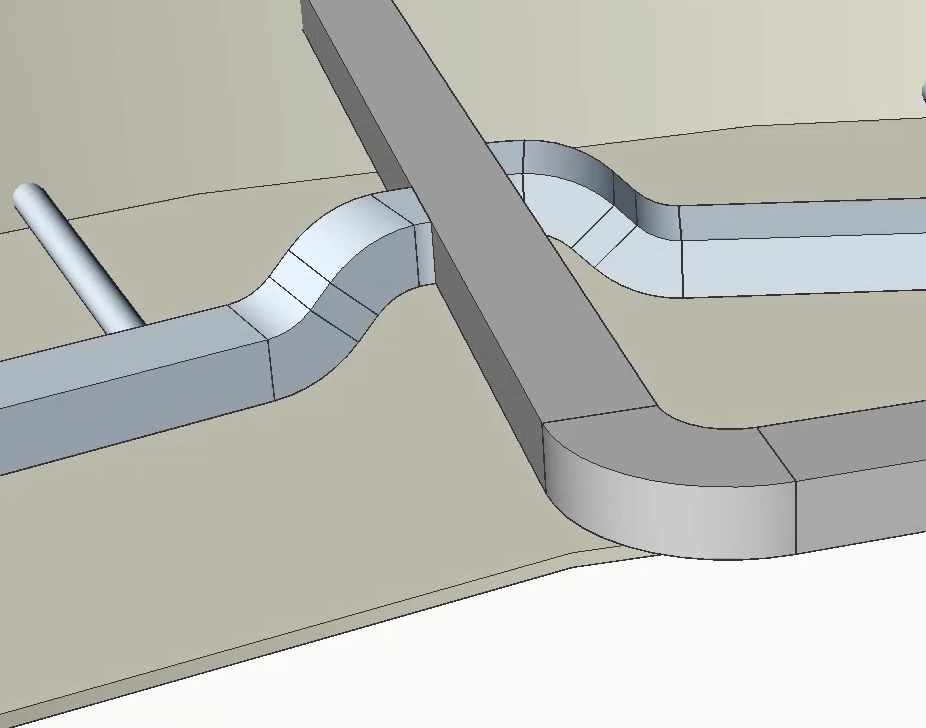
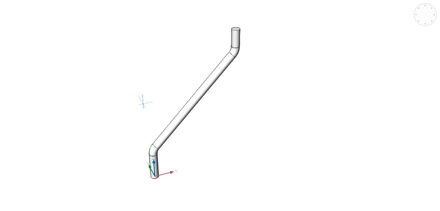
从流量终端创建风管。
启动BimLinearSolid命令并选择流连接点。
该连接点包含配置文件信息,因此软件会自动创建预定义的圆形风管。将风管的长度设为1。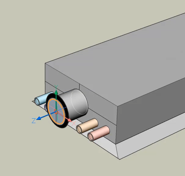
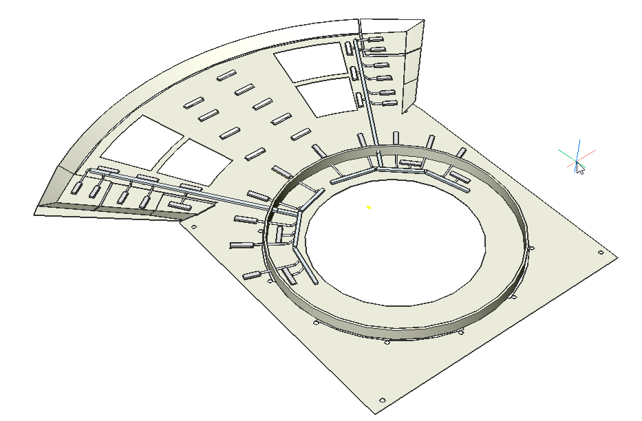
将管道从流量终端连接到矩形主管道。
选择主风管和流量终端的风管,然后启动BimFlowConnect命令。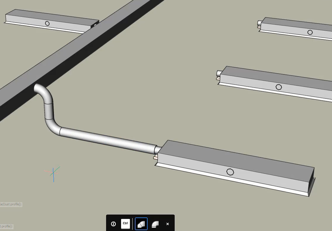
将所有其他流量端子立即连接到矩形风管。
选择其他流量终端和矩形风管,然后启动BimFlowConnect命令。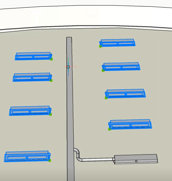
THCAD使用来自流动连接点的信息来确定用于与主管道连接的管道类型。
注意:背面的流量端子连接到矩形风管的背面。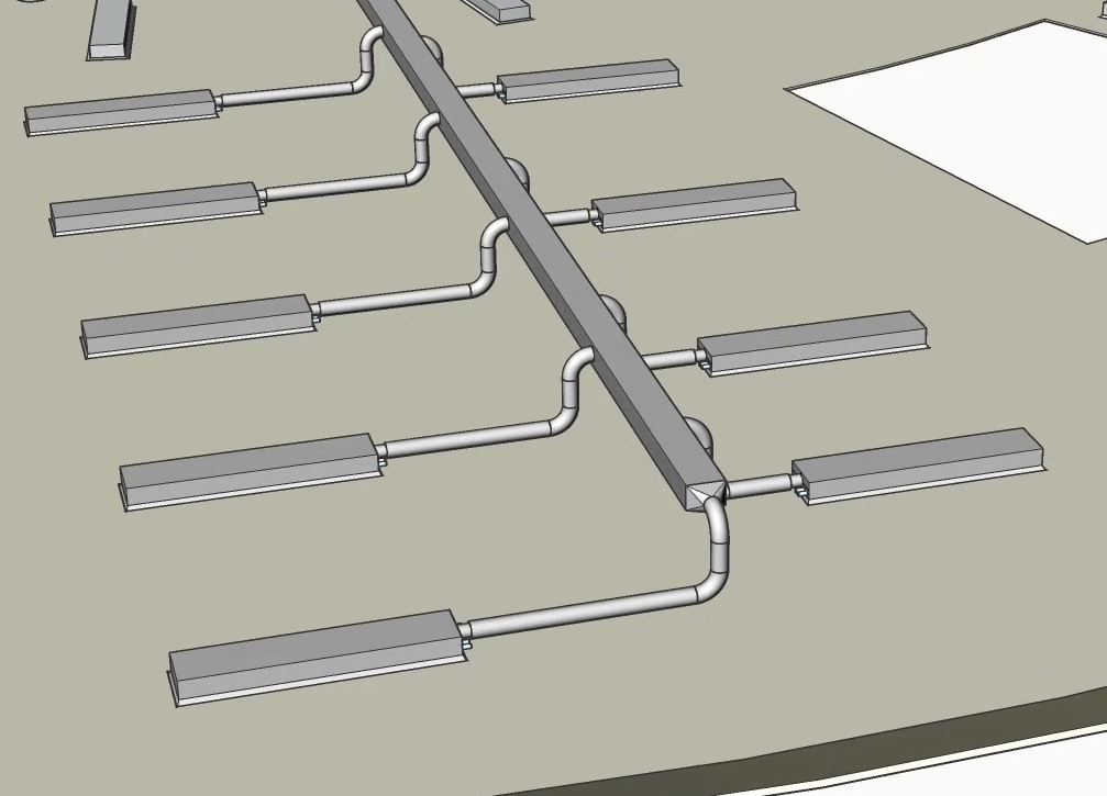
过程:使用MEP建模工具更改配置文件
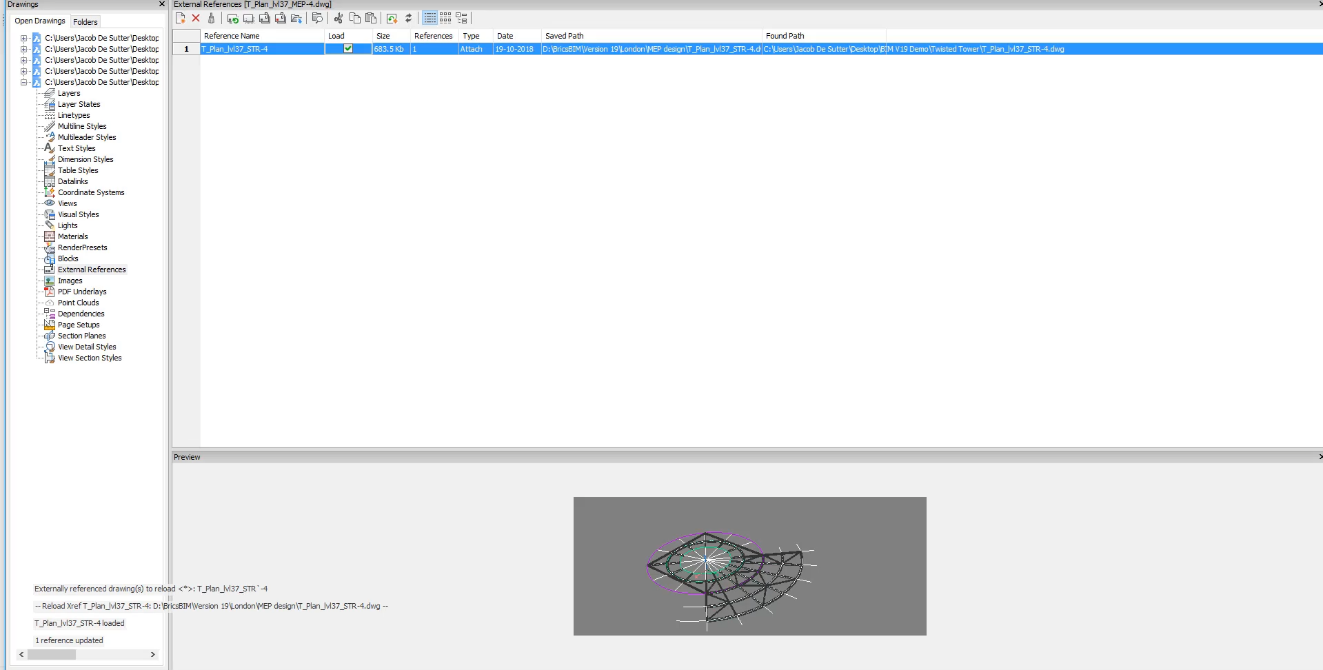
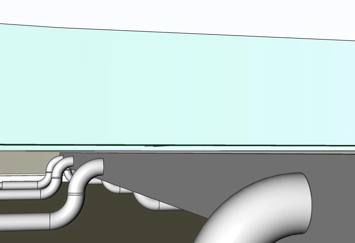
键入外部参照的命令行,并检查称重旁边的框结构模型加载结构图。

使用MultiSlice划分矩形风管。在动态尺寸字段中
输入3,然后按Enter键结束命令。
更改矩形风管的位置,以免干扰结构模型。
选择风管的上表面并启动“拖动”命令。
注意: THCAD保留与圆形风管的连接。如果要断开导管的连接,可以通过按CTRL键来更改此设置。
将风管向下移动0.23。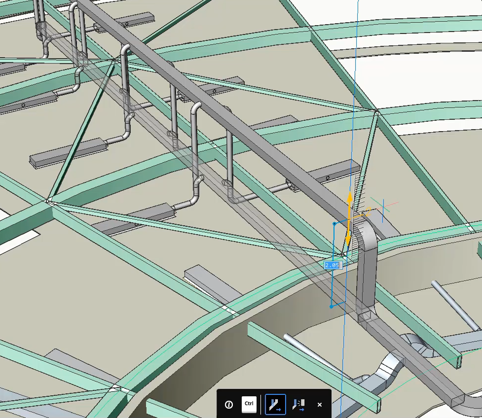
结构模型不再干扰MEP模型,同时保留了流路终端的导管与主矩形导管之间的连接。
过程:使用Bimstretch修改流线段
打开一个新工程图。
单击屏幕右侧的“配置文件面板”,以打开它。
Note: If the Profile Panel icon isn’t visible yet, right-click on the ribbon and check Profiles in the context menu under
Filter on the HVAC standard. These profiles will be automatically classified as flow segments once they are dragged into the model space.
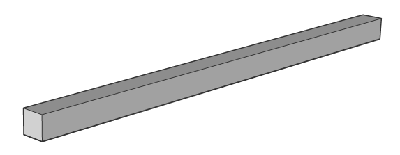
Search for the profile HVAC Rectangular Duct 10''x10'' in the Profiles panel and drag the profile in the model space.
Select a starting point and draw a profile. Press enter to stop drawing with this profile. Your model should look like this:

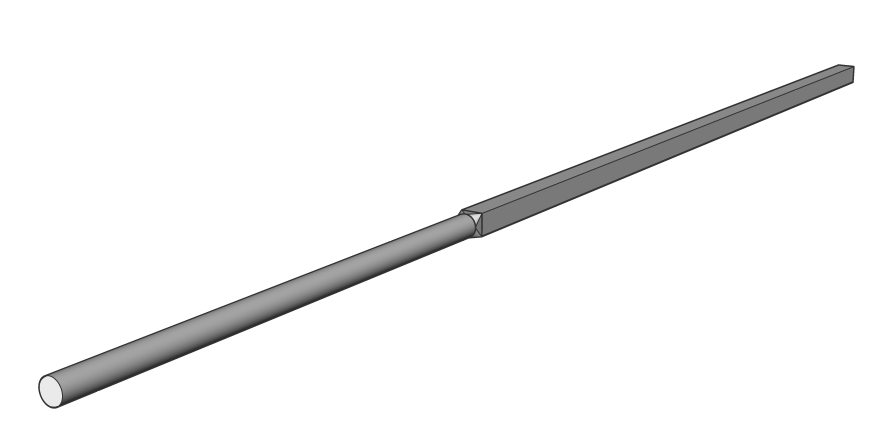
Search for the profile HVAC Round Duct 8'' in the Profiles Panel and drag the profile in the model space.
Click on the end of the Rectangular profile, after hovering on its profile face.
注意:要轻松捕捉矩形轮廓的末端,请打开“显示轴”设置。
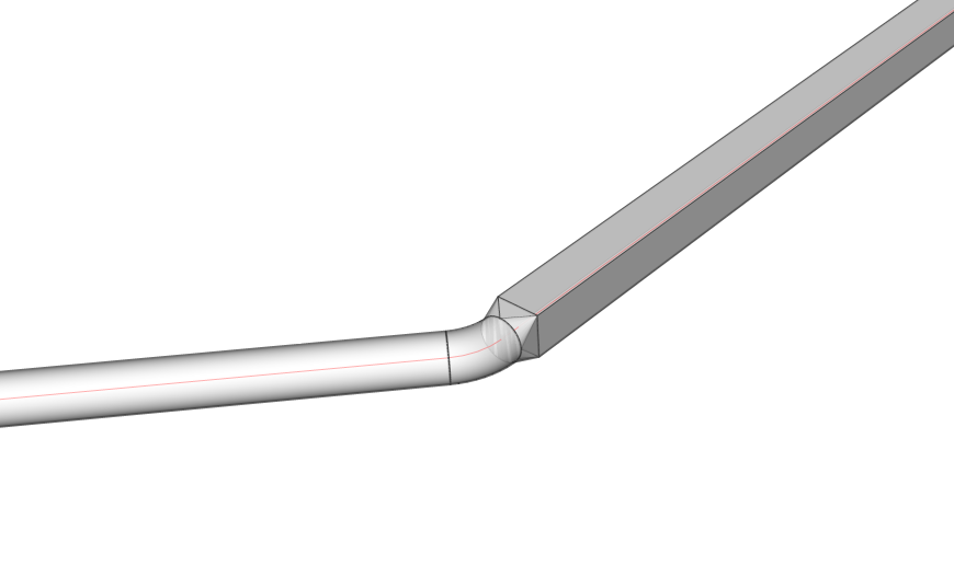
确保沿着与矩形相同的轴绘制圆形轮廓。接受圆形轮廓的最后一点后,它将通过自动生成的变径管连接到矩形轮廓。
注意:如果您选择使用非HVAC轮廓进行绘图,则不会自动分类为“流线段”,也不会立即建立连接。您仍然可以通过BimClassify命令手动对配置文件进行分类,然后使用BimFlowConnect通过reducer连接两者。
注意:确保已启用“显示面”和“末端”以及“显示轴”。选择两个线段的连接端。
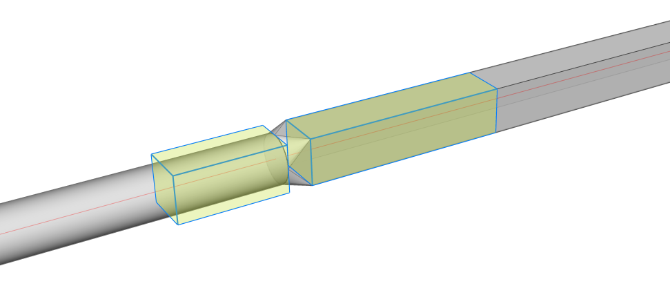
启动BimStretch工具。
将光标悬停在一侧,然后单击所需的位置。THCAD自动将2个流量段拉伸到它们的新位置,并在中间添加一个额外的弯曲流量配件。